Exercise: Construct IoT hardware
In this unit, you'll learn about the hardware used in this module. You'll then construct the device used to monitor cave conditions and control the fan.
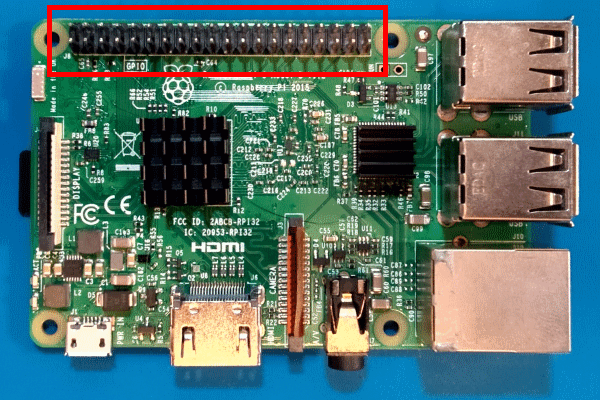
The GPIO header
This array of pins on the Raspberry Pi is called the General Purpose Input/Output (GPIO) header.
This versatile pin header supports communication using various protocols. You'll learn more about the supported protocols in the next unit.
Breadboards
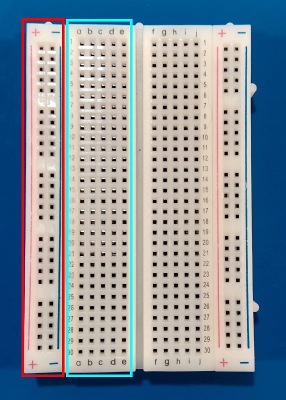
A breadboard is a rapid prototyping tool for circuits.
The breadboard is organized in rows and columns called strips. The bus strips on the edges (indicated in the preceding image in red) provide a continuous connection over the length of the breadboard. They're used to supply power for the circuit. The socket strips toward the middle of the breadboard (cyan) allow components to be connected together without soldering or wires.
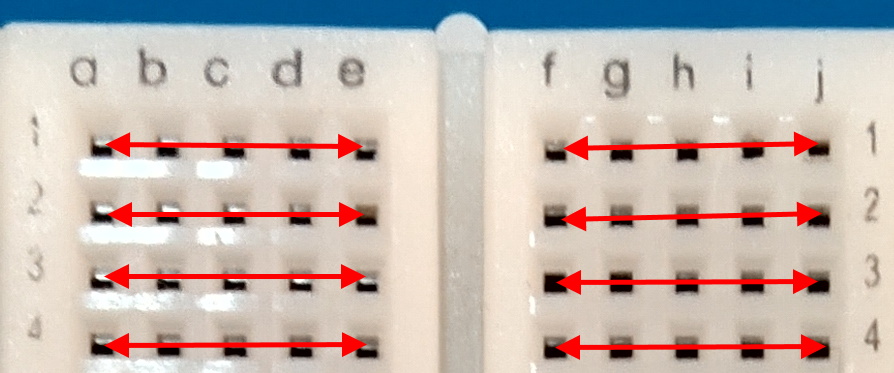
For example, any pin plugged into row 1, column a in the previous image would also be connected to any pin plugged into row 1, columns b-e. On the other side of the divider, row 1 columns f-j are similarly connected.
You can pair a breadboard with a GPIO breakout board to simplify prototyping with GPIO pins.
Measure environmental conditions
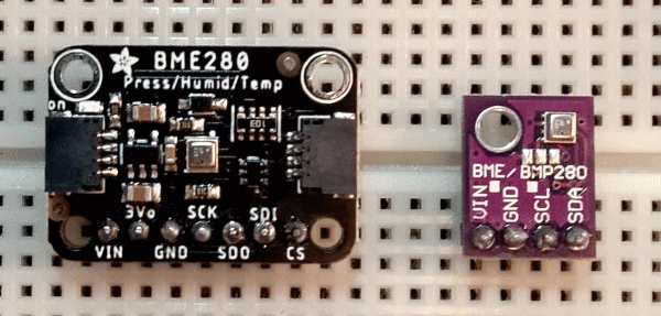
To measure temperature and humidity, you'll use a commonly available low-cost environmental sensor, the BME280.
Your BME280 sensor chip is already installed on a breakout board. All you need to do is connect the breakout board to the Inter-Integrated Circuit (I2C) bus on the Raspberry Pi. The I2C bus is accessible on the GPIO header.
Note
There are many manufacturers of BME280 breakouts. Most designs are similar, and the manufacturer shouldn't make any difference to the functionality. This module was built with the Adafruit example in the prerequisites. Ensure your BME280 breakout includes an Inter-Integrated Circuit (I2C) interface.
Tip
Most BME280 breakouts are sold with the pin header unattached. As a consequence, most require soldering to assemble. If you don't know how to solder, don't be discouraged! Soldering isn't as hard as you might think! There are many tutorials and videos to get you started.
Control fans
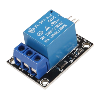
The device you're going to build is slightly different than what you'd build for a real-world device. In a real-world scenario, you'd use a relay module like this to control power to the fan:
A relay is an electromagnetic switch that allows you to use small currents to control larger currents. When a small current is passed through the low-voltage input on the relay, it activates the switch. Activating the switch completes a different circuit.
A real-world device might use this relay to control power to a fan. A fan large enough to maintain humidity in a cave would generally require a large AC current. For safety purposes, and to keep focus on the code, your device is going to use an LED to represent a relay. An illuminated LED will indicate that the relay is "on."
To activate the LED, your code will activate a GPIO pin for output. The GPIO pin will send current to the LED, which will illuminate. This is the same process you'd use to send current to a relay and activate the switch.
Exercise: Construct the IoT device
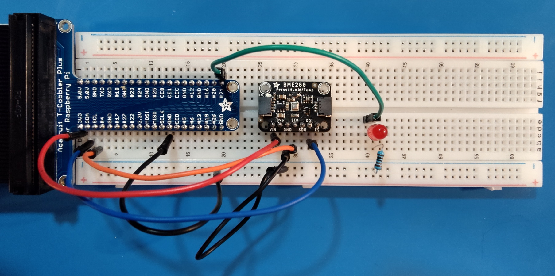
You're going to use a breadboard to build the device. The completed breadboard should look like the following diagram.
Refer to the preceding diagram as you construct your device.
Position the GPIO breakout and BME280 breakout on the breadboard as shown.
Position jumper wires on the breadboard to connect the BME280 to the GPIO breakout.
GPIO pin BME280 breakout pin Diagram color 3.3V VIN (sometimes labeled 3V3) Red Ground GND Black SDA SDI (sometimes labeled SDA) Blue SCL SCK (sometimes labeled SCL) Orange Position jumper wires on the breadboard to connect the LED to the GPIO breakout.
Connect this... ...to this Diagram color GPIO pin 21 LED anode
(longer, positive lead)Green LED cathode
(shorter, negative lead)1.0K ohm resistor
(either end)N/A 1.0K ohm resistor
(other end)Ground N/A Note
You need the resistor to ensure the LED isn't burnt out due to excessive current. You don't need a resistor in a real-world relay scenario.
Connect the Raspberry Pi
While the Raspberry Pi is powered off, use a ribbon cable to connect the GPIO breakout to the Raspberry Pi's GPIO header. Power on the Raspberry Pi.
In the next unit, you'll learn about the .NET IoT Libraries.
