This article is intended for network architects that want to design Software-defined Wide Area Networks (SD-WANs) to connect on-premises facilities with each other and with Azure. It describes an architecture that lets Azure customers use their existing investments in the platform, by building efficient, global SD-WAN overlays on top of the Microsoft backbone.
Applicable scenarios
The recommendations in this article are vendor-agnostic and applicable to any non-Microsoft SD-WAN technology that meets two basic prerequisites:
- Reliance on tunneling protocols that use Transmission Control Protocol (TCP) or User Datagram Protocol (UDP) as the underlying transport, such as being tunnel-mode IPSec ESP with NAT-Traversal.
- Border Gateway Protocol (BGP) v4 support for route exchange with external entities. No assumptions are made on the routing protocol used by the non-Microsoft SD-WAN devices to exchange routing information between each other.
Customers who adhere to these recommendations can use their SD-WAN technology of choice to achieve the following goals:
- Integrate SD-WAN products in an existing Azure hub and spoke network, by automating route exchange between Azure Virtual Network and SD-WAN devices.
- Optimize connectivity (both to Azure and on-premises datacenters) for branches with local internet breakouts. The reach of the Microsoft backbone, combined with its capacity, resiliency and "cold potato" routing policy suggests that it can be used as a high-performance underlay for global SD-WANs.
- Use the Microsoft backbone for all Azure-to-Azure traffic (cross region and cross geography).
- Use existing Multi-Protocol-Label-Switching (MPLS) networks as high-performance underlays. It can also be used to replace an existing MPLS network in a phased approach that minimizes the effect on the business.
The following sections assume that the reader is familiar with the basics of the SD-WAN paradigm and with the architecture of the Microsoft backbone. The Microsoft backbone interconnects Azure regions with each other and with the public internet.
Architecture
Organizations with global presence and a multi-region Azure footprint typically use a combination of connectivity services to implement their corporate networks and to connect to the Microsoft backbone:
- Dedicated connectivity services, such as MPLS Internet-Protocol-Virtual-Private-Networks (IPVPNs), can be used at the largest sites, such as datacenters or headquarters.
- Large sites can include dedicated connectivity to the Microsoft backbone through ExpressRoute circuits, using one of the supported connectivity models. More specifically, a site can use dedicated point-to-point circuits to connect to the nearest ExpressRoute peering location. Or it can apply its MPLS IPVPN to access ExpressRoute circuits provided by the MPLS carrier.
- Branch offices that only have internet connectivity might use IPSec VPNs to connect to the closest on-premises datacenter and use that datacenter's ExpressRoute connection to access Azure resources. Or they might use IPSec VPNs to directly connect to Azure hub and spoke networks.
SD-WAN projects can have different scopes in terms of which traditional network services they intend to replace. Some organizations might want to stick to dedicated links or MPLS for large facilities and deploy an SD-WAN only to replace legacy internet-based IPSec VPNs in small sites. Other organizations might want to extend their SD-WAN to MPLS-connected sites and use the existing MPLS network as a high-performance underlay. Finally, some organizations might want to dismiss their MPLS IPVPNs. or any dedicated connectivity service, to embrace the SD-WAN paradigm. In this way, they can build their entire corporate network as a logical overlay on top of public or shared underlays (the public internet and the Microsoft backbone).
The architecture described in this article supports all the scopes listed previously and is based on the following principles:
- SD-WAN devices are deployed as Network Virtual Appliances (NVAs) in each Azure region's hub and spoke network and configured as SD-WAN hubs that terminate tunnels from on-premises sites.
- SD-WAN devices in Azure are configured to establish tunnels with each other, thus creating a fully meshed hub-to-hub overlay that can efficiently transport traffic among Azure regions, and relay traffic between geographically distant on-premises sites, on top of the Microsoft backbone.
- SD-WAN devices are deployed in all on-premises sites covered by the SD-WAN solution and configured to establish tunnels to the SD-WAN NVAs in the closest Azure regions. Different sites can use different transport services as an underlay for the tunnels, such as public internet, ExpressRoute connectivity, and so on.
- Traffic from a site to any destination, whether in Azure or in another on-premises site, is routed to the SD-WAN NVAs in the closest Azure region. Then it routes through the hub-to-hub overlay.
SD-WAN products can use proprietary protocols and features to detect, once dynamically established, direct tunnels between two sites can provide better performance than relaying traffic via SD-WAN NVAs in Azure.
The high-level architecture of a global SD-WAN that uses the Microsoft backbone, the public internet, and dedicated ER connections as underlays is shown in the following picture.
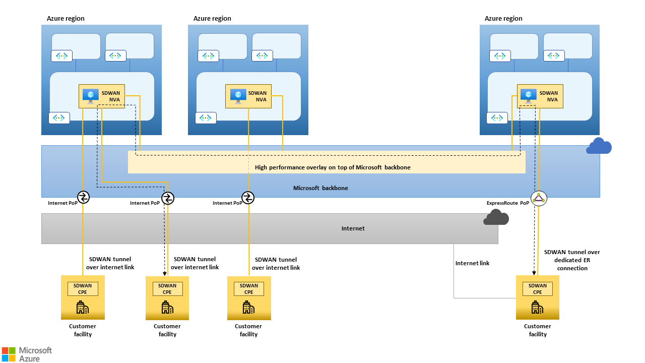 Figure 1: High-level architecture of a global SD-WAN that uses the Microsoft backbone, the public internet and dedicated ER connections as underlays. The black dashed line shows how traffic between two on-premises sites can be routed through SD-WAN NVAs deployed in Azure regions geographically close to the sites. The Microsoft backbone, due to its reach, capacity and "cold potato" routing policy can lead to substantially better/predicatable performance than the public internet, especially for long-haul connections.
SD-WAN products in Azure hub-and-spoke networks
This section provides recommendations for deploying non-Microsoft SD-WAN CPE devices as NVAs in an existing hub and spoke Azure network.
SD-WAN NVAs in the hub virtual network
Hub and Spoke is the topology that Microsoft recommends for building scalable networks in an Azure region using customer-managed virtual networks. The hub virtual network hosts shared components such as non-Microsoft NVAs and native services that provide network functions, like firewalling, load balancing, and connectivity to on-premises sites via site-2-site VPNs or ExpressRoute. The hub virtual network is the natural location for SD-WAN NVAs, which ultimately are non-Microsoft gateways providing access to remote networks.
SD-WAN NVAs should be deployed in hub virtual networks as follows:
- One single network interface controller (NIC) is used for all SD-WAN traffic. Other NICs, such as a management NIC, can be added to meet security and compliance requirements or to adhere to vendor guidelines for Azure deployments.
- The NIC used for SD-WAN traffic must be attached to a dedicated subnet. The size of the subnet must be defined based on the number of SD-WAN NVAs deployed to meet high availability (HA) and scale or throughput requirements, discussed later in this article.
- Network Security Groups (NSGs) must be associated to the SD-WAN traffic NIC, either directly or at the subnet level. This association allows connections from remote on-premises sites over the TCP/UDP ports used by the SD-WAN solution.
- IP Forwarding must be enabled on the NIC used for SD-WAN traffic.
Azure Route Server in the hub virtual network
Azure Route Server automates route exchange between SD-WAN NVAs and the Azure Software Defined Networking (SDN) stack. Route Server supports BGP as a dynamic routing protocol. By establishing BGP adjacencies between Route Server and the SD-WAN NVA(s):
- Routes for all the on-premises sites connected to the SD-WAN are injected in the virtual network's route tables and learned by all Azure VMs.
- Routes for all IP prefixes included in the address space of virtual networks are propagated to all SD-WAN-connected sites.
Route Server should be configured as follows.
- It must be deployed in a dedicated subnet in the hub virtual network as per Create and configure Route Server using the Azure portal.
- In order to enable automated route exchange for all spoke virtual networks, virtual network peering must be configured to allow the spoke virtual networks to use the hub virtual network's gateway and Route Server. Details available in the Azure Route Server FAQ.
- As Route Server and the SD-WAN NVAs are attached to different subnets, BGP sessions between Route Server and SD-WAN NVAs must be configured with eBGP multihop support. Any number of hops between 2 and the maximum supported by the SD-WAN NVA can be set. Details about configuring BGP adjacencies for Route Server are available at Create and configure Route Server using the Azure portal.
- Two
/32static routes must be configured on the SD-WAN NVA for the BGP endpoints exposed by Route Server. This configuration ensures that the NVA's route table always contains routes for its multihop (not directly connected) BGP peers.
Route Server isn't in the data path. It's a control plane entity. It propagates routes between the SD-WAN NVA and the virtual network SDN stack, but actual traffic forwarding between the SD-WAN NVA and the virtual machines in the virtual network is done by the Azure SDN stack, as shown in the following figure. To obtain this routing behavior, Route Server injects all the routes it learns from the SD-WAN NVAs with next hop set to the NVA's own address.
Route Server doesn't support IPv6 as of now. This architecture is only for IPv4.
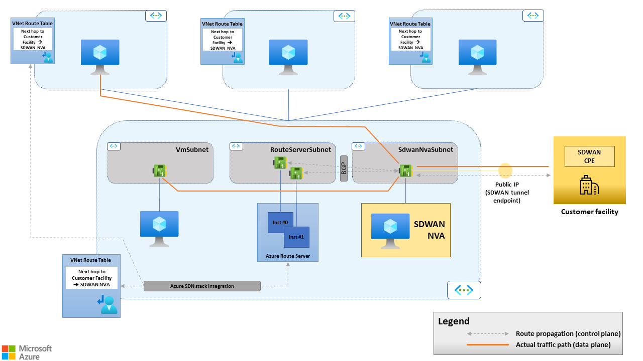 Figure 2. Route Server supports route propagation between the SD-WAN CPE and the virtual network SDN stack, but it doesn't forward traffic between the SD-WAN CPE and the virtual machines in the virtual network.
High availability for SD-WAN NVAs with Route Server
Route Server has built-in HA. Two compute nodes back a single instance of Route Server. They're deployed in different availability zones, for the regions that have availability zone support, or in the same availability set. They expose two BGP endpoints. HA for the SD-WAN NVAs is achieved by deploying multiple instances in different availability zones, for regions that support them, or in the same availability set. Each SD-WAN NVA establishes two BGP sessions with both endpoints exposed by Route Server.
The architecture described in this article doesn't rely on Azure Load Balancers. More specifically:
No public load balancers expose SD-WAN tunnel endpoints. Each SD-WAN NVA exposes its own tunnel endpoint. Remote peers establish multiple tunnels, one for each SD-WAN NVA in Azure.
No internal load balancers distribute the traffic originated by Azure VMs to the SD-WAN NVAs. Route Server and the Azure SDN stack support Equal-Cost Multipath (ECMP) routing. If multiple NVAs set up BGP adjacencies with Route Server and announce routes for the same destinations (as in, remote networks and sites connected to the SD-WAN) by using the same degree of preference, Route Server:
- Injects multiple routes for those destinations in the virtual network's route table.
- Sets each route to use a different NVA as the next hop.
The SDN stack then distributes traffic to those destinations across all available next hops.
The resulting HA architecture is shown in the following figure:
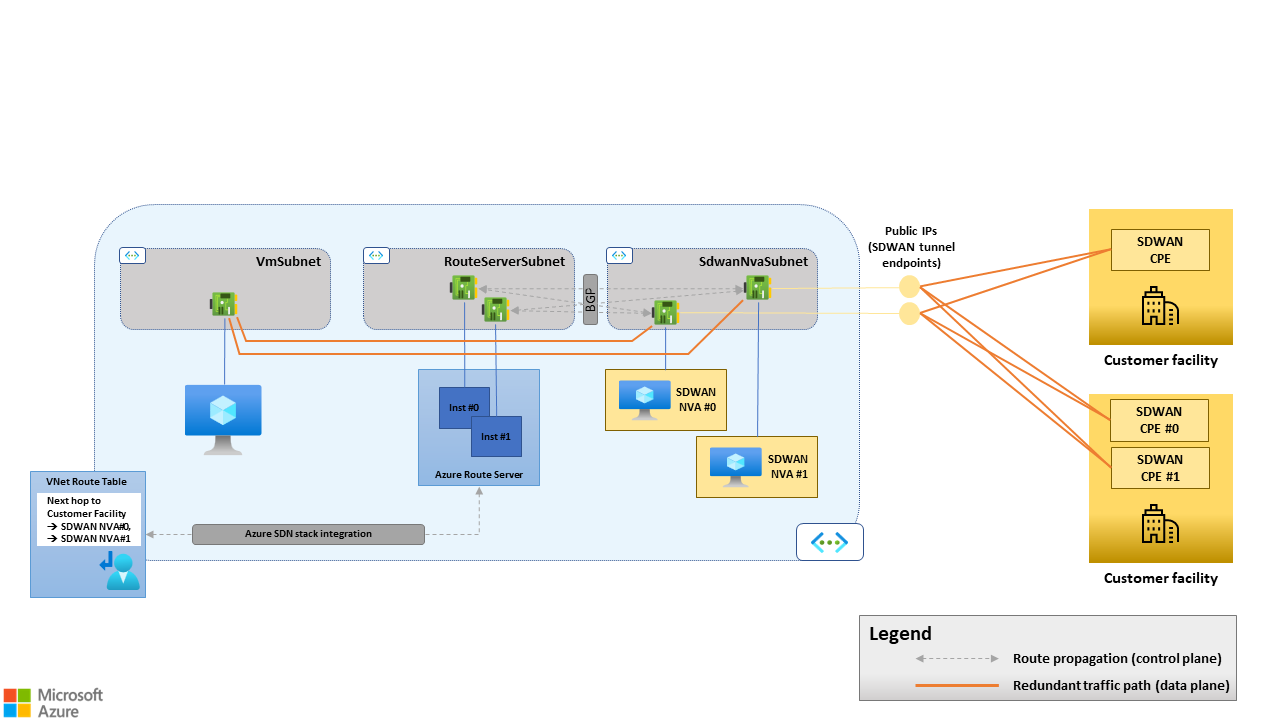 Figure 3. Route Server supports Equal-Cost Multipath (ECMP) routing. Azure Load Balancers aren't needed when multiple SD-WAN NVAs are used for availability and/or scalability purposes.
N-active versus active stand-by high availability
When you use multiple SD-WAN NVAs and peer them with Route Server, BGP drives the failover. If an SD-WAN NVA goes offline, it stops advertising routes to Route Server. The routes learned from the failed device are then withdrawn from the virtual network's route table. So, if an SD-WAN NVA no longer provides connectivity to remote SD-WAN sites because of a fault, in the device itself or in the underlay, it no longer shows up as a possible next hop toward the remote sites in the virtual network's route table. All the traffic goes to the remaining healthy devices. For more information on route propagation between SD-WAN NVAs and Route Server, see Routes advertised by a BGP peer to Route Server.
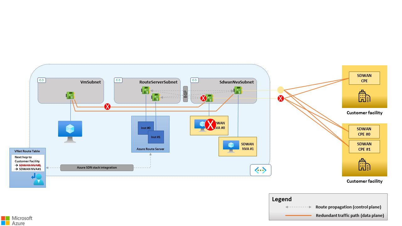 Figure 4. BGP-driven failover. If SD-WAN NVA #0 goes offline, its BGP sessions with Route Server close. SD-WAN NVA #0 is removed from the virtual network's route table as a possible next hop for traffic going from Azure to on-premises site.
BGP-driven failover and ECMP routing naturally enable N-active HA architectures with N devices concurrently processing traffic. But you can also use BGP to implement active and passive HA architectures: configure the passive device to announce to Route Server the routes with a lower degree of preference than its active peer. Route Server discards the routes received from the passive device if it receives from the active device any routes for the same destinations with a higher degree of preference. And it plumbs only the latter routes in the virtual network's route table.
If the active device fails or withdraws some of its routes, the Route Server:
- Selects the corresponding routes announced by the passive device.
- Plumbs the routes in the virtual network's route table.
The only BGP attributes that SD-WAN NVAs can use to express a degree of preference for the routes that they announce to Route Server is AS Path.
We recommend N-active HA architectures because they enable optimal resource use (there are no stand-by SD-WAN NVAs) and horizontal scalability. To increase throughput, multiple NVAs can run in parallel, up to the maximum number of BGP peers supported by Route Server. For more information, see BGP peers. But the N-active HA model requires the SD-WAN NVAs to act as stateless, layer 3 routers. When multiple tunnels to a site exist, TCP connections can be routed asymmetrically. That is, the ORIGINAL and REPLY flows of the same TCP connection can be routed through different tunnels and different NVAs. The following figure shows an example of an asymmetrically routed TCP connection. Such routing asymmetries are possible for TCP connections initiated on either the virtual network or on-premises site.
 Figure 5. Asymmetric routing in active/active HA architectures. SD-WAN NVA #0 and SD-WAN NVA #1 announce the same route for destination 192.168.1.0/24 (remote SD-WAN site) with the same AS Path length to Route Server. The ORIGINAL flow (from SD-WAN remote site to Azure, red path) is routed via the tunnel terminated, on the Azure side, by SD-WAN NVA #1. The on-premises SD-WAN CPE selects this tunnel. The Azure SDN stack routes the REPLY flow (from Azure to remote SD-WAN site, green path) to SD-WAN NVA #0, which is one of the possible next hops for 192.168.1.0/24, according to the virtual network's route table. It isn't possible to guarantee that the next hop chosen by the Azure SDN stack is always the same SD-WAN CPE that received the ORIGINAL flow.
Active and passive HA architectures should only be considered when SD-WAN NVAs in Azure perform other network functions that require routing symmetry, such as stateful firewalling. We don't recommend this approach because of its implications on scalability. Running more network functions on SD-WAN NVAs increases resource consumption. At the same time, the active and passive HA architecture allows having one single NVA processing traffic at any point in time. That is, the whole SD-WAN layer can only be scaled up to the maximum Azure VM size it supports, not scaled out. Run stateful network functions that require routing symmetry on separate NVA clusters that rely on Standard Load Balancer for n-active HA.
ExpressRoute connectivity considerations
The architecture described in this article lets customers fully embrace the SD-WAN paradigm and build their corporate network as a logical overlay on top of the public internet and the Microsoft backbone. It also supports using dedicated Expressroute circuits to address specific scenarios, described later.
Scenario #1: ExpressRoute and SD-WAN coexistence
SD-WAN solutions can coexist with ExpressRoute connectivity when SD-WAN devices are deployed only in a subset of sites. For example, some organizations might deploy SD-WAN solutions as a replacement for traditional IPSec VPNs in sites with internet connectivity only. Then they use MPLS services and ExpressRoute circuits for large sites and datacenters, as shown in the following figure.
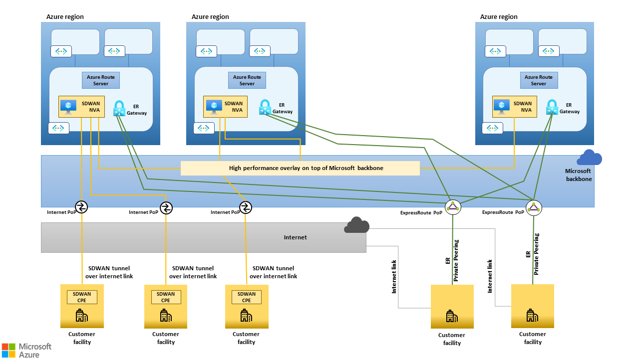 Figure 6. SD-WAN solutions can coexist with ExpressRoute connectivity when SD-WAN CPE devices are deployed only in a subset of sites.
This coexistence scenario requires SD-WAN NVAs deployed in Azure to be capable of routing traffic between sites connected to the SD-WAN and sites connected to ExpressRoute circuits. Route Server can be configured to propagate routes between ExpressRoute virtual network gateways and SD-WAN NVAs in Azure by enabling the AllowBranchToBranch feature, as documented here. Route propagation between the ExpressRoute virtual network gateway and the SD-WAN NVA(s) happens over BGP. Route Server establishes BGP sessions with both and propagates to each peer the routes learned from the other. The platform manages the BGP sessions between Route Server and the ExpressRoute virtual network gateway. Users don't need to configure them explicitly, but only to enable the AllowBranchToBranch flag when deploying Route Server.
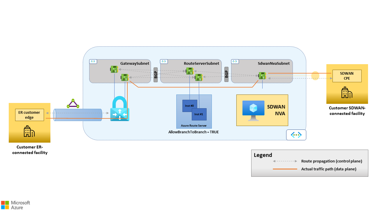 Figure 7. Route propagation between the ExpressRoute virtual network gateway and the SD-WAN NVA(s) happens over BGP. Route Server establishes BGP sessions with both and propagates routes in both directions when configured with "AllowBranchToBranch=TRUE". Route Server act as a route reflector, that is, it isn't part of the data path.
This SD-WAN and ExpressRoute coexistence scenario enables migrations from MPLS networks to SD-WAN. It offers a path between legacy MPLS sites and newly migrated SD-WAN sites, eliminating the need to route traffic through on-premises datacenters. This pattern can be used not only during migrations but also in scenarios arising from company mergers and acquisitions, providing a seamless interconnection of disparate networks.
Scenario #2: Expressroute as an SD-WAN underlay
If your on-premises sites have ExpressRoute connectivity, you can configure SD-WAN devices to set up tunnels to the SD-WAN hub NVAs running in Azure on top of the ExpressRoute circuit or circuits. ExpressRoute connectivity can be done through point-to-point circuits or an MPLS network. You can use both ExpressRoute private peering and the Microsoft peering.
Private peering
When you use the ExpressRoute private peering as the underlay, all on-premises SD-WAN sites establish tunnels to the SD-WAN hub NVAs in Azure. No route propagation between the SD-WAN NVAs and the ExpressRoute virtual network gateway is needed in this scenario (that is, Route Server must be configured with the "AllowBranchToBranch" flag set to false).
This approach requires proper BGP configuration on the customer- or provider-side routers that terminate the ExpressRoute connection. In fact, the Microsoft Enterprise Edge Routers (MSEEs) announce all the routes for the virtual networks connected to the circuit (either directly or via virtual network peering). But in order to forward traffic destined to virtual networks through an SD-WAN tunnel, the on-premises site should learn those routes from the SD-WAN device - not the ER circuit.
Therefore, the customer-side or provider-side routers that terminate the ExpressRoute connection must filter out the routes received from Azure. The only routes configured in the underlay should be ones that allow the on-premises SD-WAN devices to reach the SD-WAN hub NVAs in Azure. Customers that want to use the ExpressRoute private peering as an SD-WAN underlay should verify that they can configure their routing devices accordingly. Doing so is especially relevant for customers who don't have direct control over their edge devices for ExpressRoute. An example is when the ExpressRoute circuit is provided by an MPLS carrier on top of an IPVPN service.
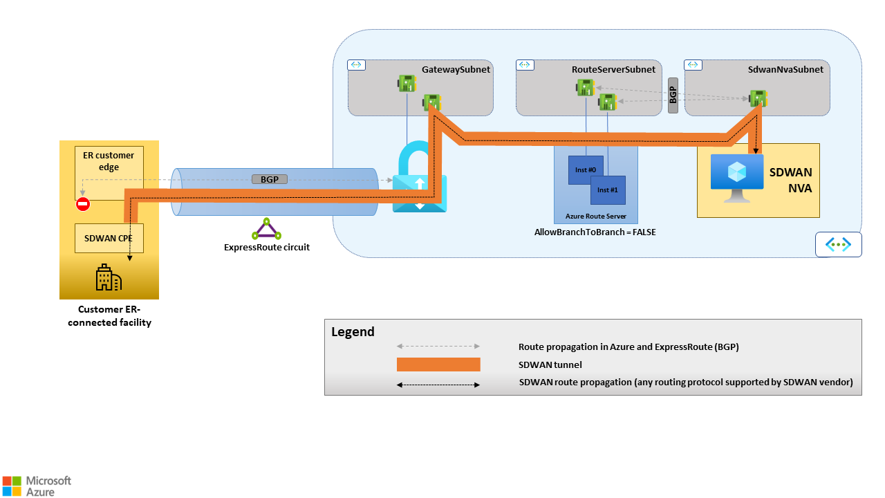 Figure 8. ExpressRoute private peering as an SD-WAN underlay. In this scenario, the customer and provider-side routers receive the routes for the virtual network that terminate the ExpressRoute connection, in the ER private peering BGP sessions, and the SD-WAN CPE. Only the SD-WAN CPE should propagate the Azure routes into the site's LAN.
Microsoft peering
You can also use the ExpressRoute Microsoft peering as an underlay for SD-WAN tunnels. In this scenario, the SD-WAN hub NVAs in Azure only expose public tunnel endpoints, which are used by both SD-WAN CPEs in internet-connected sites, if any, and by SD-WAN CPEs in Expressroute-connected sites. Although the ExpressRoute Microsoft peering has more complex prerequisites than the private peering, we recommend using this option as an underlay because of these two advantages:
It doesn't require Expressroute virtual network gateways in the hub virtual network. It removes complexity, reduces cost, and lets the SD-WAN solution scale beyond the bandwidth limits of the gateway itself when you don't use ExpressRoute FastPath.
It provides a clean separation between overlay and underlay routes. The MSEEs only announce the Microsoft network's public prefixes to the customer or provider edge. You can manage those routes in a separate VRF and propagate only to a DMZ segment of the site's LAN. SD-WAN devices propagate the routes for the customer's corporate network in the overlay, including routes for virtual networks. Customers considering this approach should verify that they can configure their routing devices accordingly or request the proper service to their MPLS carrier.
MPLS considerations
Migration from traditional MPLS corporate networks to more modern network architectures based on the SD-WAN paradigm requires a significant effort and a considerable amount of time. The architecture described in this article enables phased SD-WAN migrations. Two typical migration scenarios are discussed later.
Phased MPLS decommissioning
Customers that want to build an SD-WAN on top of the public internet and the Microsoft backbone, and completely decommission MPLS IPVPNs or other dedicated connectivity services, can use the ExpressRoute and SD-WAN coexistence scenario described in the previous section during the migration. It enables SD-WAN-connected sites to reach sites still connected to the legacy MPLS. As soon as a site is migrated to the SD-WAN and CPE devices are deployed, its MPLS link can be decommissioned. The site can access the entire corporate network through its SD-WAN tunnels to the closest Azure regions.
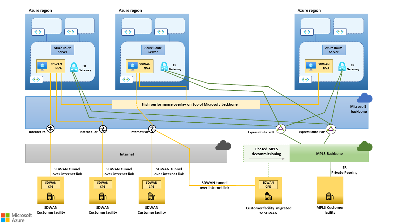 Figure 9. The "ExpressRoute and SD-WAN coexistence" scenario enables phased MPLS decommissioning.
When all the sites are migrated, the MPLS IPVPN can be decommissioned, along with the ExpressRoute circuits that connect it to the Microsoft backbone. ExpressRoute virtual network gateways are no longer needed and can be deprovisioned. The SD-WAN hub NVAs in each region become the only entry point into that region's hub and spoke network.
MPLS integration
Organizations that don't trust public and shared networks to provide the desired performance and reliability might decide to use an existing MPLS network as an enterprise-class underlay. Two options are:
- A subset of sites like datacenters or large branch offices.
- A subset of connections, typically latency-sensitive or mission-critical traffic.
The scenario Expressroute as an SD-WAN underlay described earlier enables SD-WAN and MPLS integration. The ExpressRoute Microsoft peering should be preferred over the private peering for the reasons discussed previously. Also, when the Microsoft peering is used, the MPLS network and the public internet become functionally equivalent underlays. They provide access to all of the SD-WAN tunnel endpoints exposed by SD-WAN hub NVAs in Azure. An SD-WAN CPE deployed in a site with both internet and MPLS connectivity can establish multiple tunnels to the SD-WAN hubs in Azure on both underlays. They can then route different connections through different tunnels, based on application-level policies managed by the SD-WAN control plane.
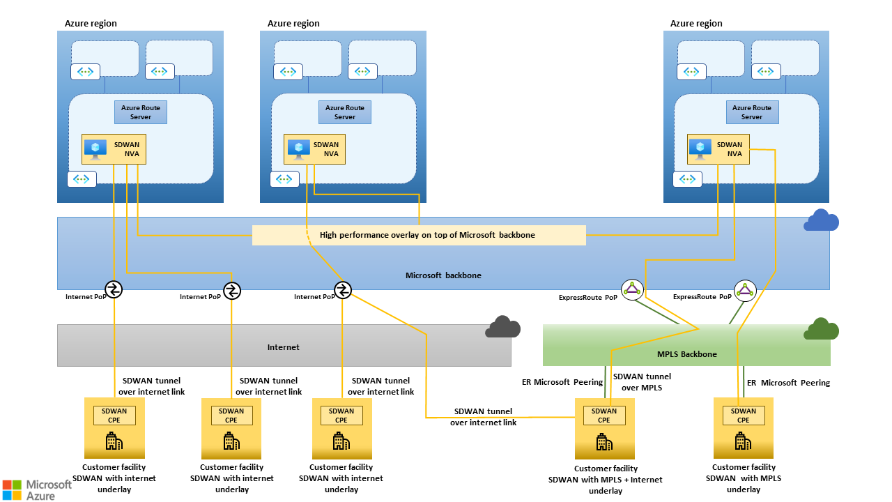 Figure 10. The "ExpressRoute as an SD-WAN underlay" scenario enables SD-WAN and MPLS integration.
Route Server routing preference
In both of the MPLS scenarios covered in the two previous sections, some branch sites can be connected both to the MPLS IPVPN and to the SD-WAN. As a result, the Route Server instances deployed in the hub virtual networks can learn the same routes from ExpressRoute Gateways and SD-WAN NVAs. Route Server routing preference allows controlling which path should be preferred and plumbed into the virtual networks' route tables. Routing preference is useful when AS Path prepending can't be used. An example is MPLS IPVPN services that don't support custom BGP configurations on the PEs that terminate ExpressRoute connections.
Route Server limits and design considerations
Route Server is the cornerstone of the architecture described in this article. It propagates routes between SD-WAN NVAs deployed in virtual networks and the underlying Azure SDN stack. It provides a BGP-based approach to running multiple SD-WAN NVAs for high availability and horizontal scalability. When you design large SD-WANs based on this architecture, the scalability limits of Route Server must be factored in.
The following sections provide guidance on scalability maximums and how to deal with each limit.
Routes advertised by a BGP peer to Route Server
Route Server doesn't define an explicit limit for the number of routes that can be advertised to ExpressRoute Virtual Network Gateways when the AllowBranchToBranch flag is set. However, ExpressRoute Gateways further propagate the routes they learn from Route Server to the ExpressRoute circuits they're connected to.
There's a limit to the number of routes that ExpressRoute Gateways can advertise to ExpressRoute circuits over the private peering, documented at Azure subscription and service limits, quotas, and constraints. When designing SD-WAN solutions based on the guidance in this article, it's critical to ensure that SD-WAN routes don't cause this limit to be hit. If hit, the BGP sessions between ExpressRoute Gateways and ExpressRoute circuits are dropped, and connectivity between virtual networks and remote networks connected via ExpressRoute is lost.
The total number of routes advertised to circuits by ExpressRoute Gateways is the sum of the number of routes learned from Route Server and the number of prefixes that make up the Azure hub and spoke network’s address space. To avoid outages due to dropped BGP sessions, we recommend you implement the following mitigations:
- Use native SD-WAN devices' features to limit the number of routes announced to Route Server, if the feature is available.
- Use Azure Monitor Alerts to proactively detect spikes in the number of routes announced by ExpressRoute Gateways. The metric to monitor is named Count of Routes Advertised to Peer, as documented in ExpressRoute monitoring.
BGP peers
Route Server can establish BGP sessions with up to a maximum number of BGP peers. This limit determines the maximum number of SD-WAN NVAs that can establish BGP adjacencies with Route Server, and therefore the maximum aggregate throughput that can be supported across all the SD-WAN tunnels. Only large SD-WANs are expected to hit this limit. No workarounds exist to overcome it, beyond creating multiple hub and spoke networks, each one with its own gateways and route servers.
Participating VMs
Virtual Network Gateways and Route Server configure the routes they learn from their remote peers for all VMs in their own virtual network and in directly peered virtual networks. To protect Route Server from excessive resource consumption due to routing updates to VMs, Azure defines a limit on the number of VMs that can exist in a single hub and spoke network. No workarounds exist to overcome this limit, beyond creating multiple hub and spoke networks, each one with its own gateways and route servers, in the same region.
Contributors
This article is maintained by Microsoft. It was originally written by the following contributors.
Principal authors:
- Federico Guerrini | Senior Cloud Solution Architect
- Khush Kaviraj | Cloud Solution Architect
To see non-public LinkedIn profiles, sign in to LinkedIn.