Designing globally available services using Azure SQL Database
Applies to: ![]() Azure SQL Database
Azure SQL Database
When building and deploying cloud services with Azure SQL Database, you use active geo-replication or failover groups to provide resilience to regional outages and catastrophic failures. The same feature allows you to create globally distributed applications optimized for local access to the data. This article discusses common application patterns, including the benefits and trade-offs of each option.
Note
If you are using Premium or Business Critical databases and elastic pools, you can make them resilient to regional outages by converting them to zone redundant deployment configuration. See Zone-redundant databases.
Scenario 1: Using two Azure regions for business continuity with minimal downtime
In this scenario, the applications have the following characteristics:
- Application is active in one Azure region
- All database sessions require read and write access (RW) to data
- Web tier and data tier must be collocated to reduce latency and traffic cost
- Fundamentally, downtime is a higher business risk for these applications than data loss
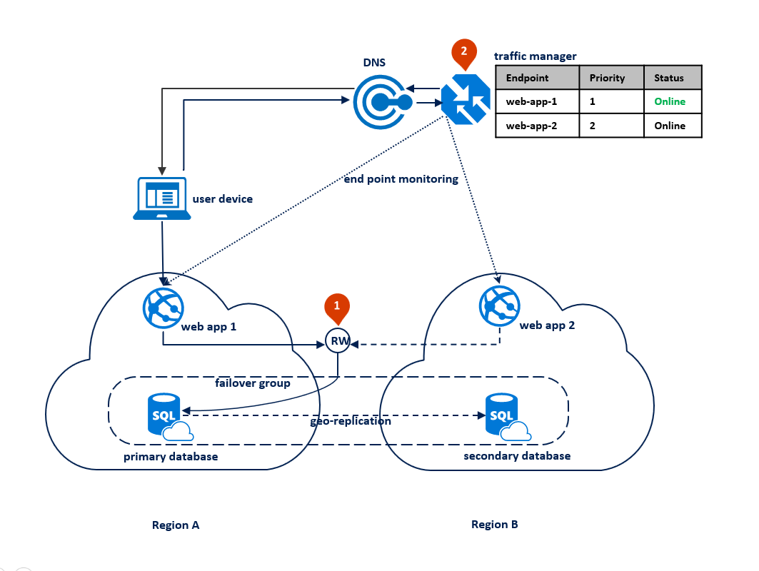
In this case, the application deployment topology is optimized for handling regional disasters when all application components need to fail over together. The diagram below shows this topology. For geographic redundancy, the application's resources are deployed to Region A and B. However, the resources in Region B are not utilized until Region A fails. A failover group is configured between the two regions to manage database connectivity, replication and failover. The web service in both regions is configured to access the database via the read-write listener <failover-group-name>.database.windows.net (1). Azure Traffic Manager is set up to use priority routing method (2).
Note
Azure Traffic Manager is used throughout this article for illustration purposes only. You can use any load-balancing solution that supports priority routing method.
The following diagram shows this configuration before an outage:
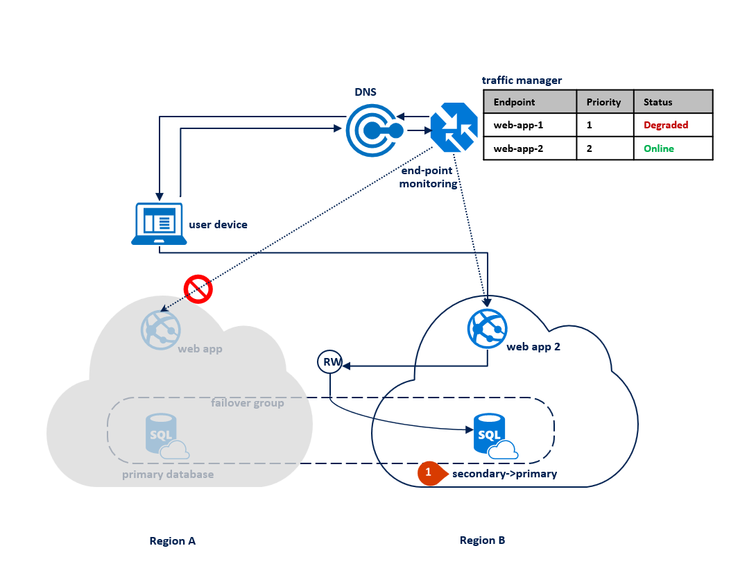
After an outage in the primary region, SQL Database detects that the primary database is not accessible and triggers failover to the secondary region based on the parameters of the automatic failover policy (1). Depending on your application SLA, you can configure a grace period that controls the time between the detection of the outage and the failover itself. It is possible that Azure Traffic Manager initiates the endpoint failover before the failover group triggers the failover of the database. In that case the web application cannot immediately reconnect to the database. But the reconnections will automatically succeed as soon as the database failover completes. When the failed region is restored and back online, the old primary automatically reconnects as a new secondary. The diagram below illustrates the configuration after failover.
Note
All transactions committed after the failover are lost during the reconnection. After the failover is completed, the application in region B is able to reconnect and restart processing the user requests. Both the web application and the primary database are now in region B and remain co-located.
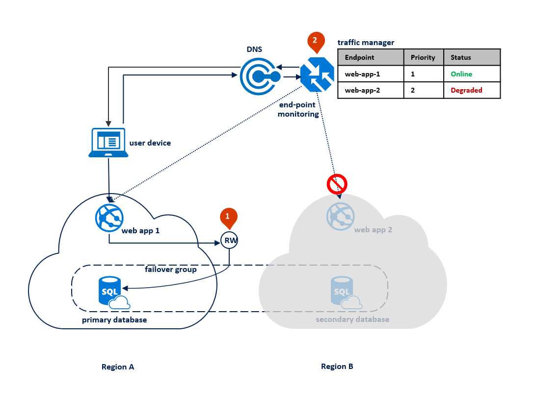
If an outage happens in region B, the replication process between the primary and the secondary database gets suspended but the link between the two remains intact (1). Traffic Manager detects that connectivity to Region B is broken and marks the endpoint web app 2 as Degraded (2). The application's performance is not impacted in this case, but the database becomes exposed and therefore at higher risk of data loss in case region A fails in succession.
Note
For disaster recovery, we recommend the configuration with application deployment limited to two regions. This is because most of the Azure geographies have only two regions. This configuration does not protect your application from a simultaneous catastrophic failure of both regions. In an unlikely event of such a failure, you can recover your databases in a third region using geo-restore operation. For more information, see Azure SQL Database disaster recovery guidance.
Once the outage is mitigated, the secondary database automatically resynchronizes with the primary. During synchronization, performance of the primary can be impacted. The specific impact depends on the amount of data the new primary acquired since the failover.
Note
After the outage is mitigated, Traffic Manager will start routing the connections to the application in Region A as a higher priority end-point. If you intend to keep the primary in Region B for a while, you should change the priority table in the Traffic Manager profile accordingly.
The following diagram illustrates an outage in the secondary region:
The key advantages of this design pattern are:
- The same web application is deployed to both regions without any region-specific configuration and doesn't require additional logic to manage failover.
- Application performance is not impacted by failover as the web application and the database are always co-located.
The main tradeoff is that the application resources in Region B are underutilized most of the time.
Scenario 2: Azure regions for business continuity with maximum data preservation
This option is best suited for applications with the following characteristics:
- Any data loss is high business risk. The database failover can only be used as a last resort if the outage is caused by a catastrophic failure.
- The application supports read-only and read-write modes of operations and can operate in "read-only mode" for a period of time.
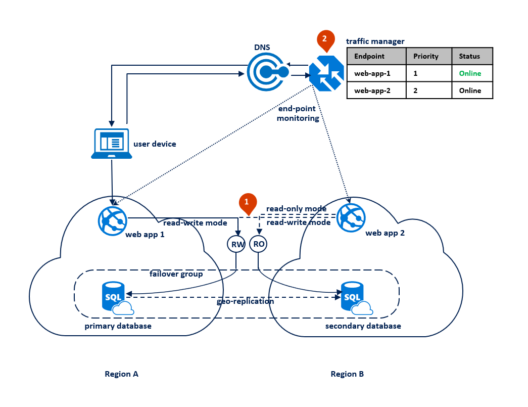
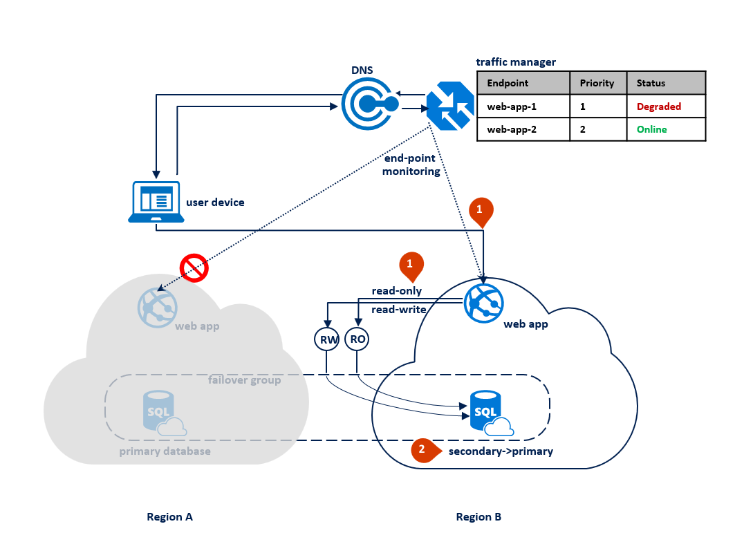
In this pattern, the application switches to read-only mode when the read-write connections start getting time-out errors. The web application is deployed to both regions and includes a connection to the read-write listener endpoint and different connection to the read-only listener endpoint (1). The Traffic Manager profile should use priority routing. End point monitoring should be enabled for the application endpoint in each region (2).
The following diagram illustrates this configuration before an outage:
When Traffic Manager detects a connectivity failure to region A, it automatically switches user traffic to the application instance in region B. With this pattern, it is important that you set the grace period with data loss to a sufficiently high value, for example 24 hours. It ensures that data loss is prevented if the outage is mitigated within that time. When the web application in region B is activated the read-write operations start failing. At that point, it should switch to the read-only mode (1). In this mode the requests are automatically routed to the secondary database. If the outage is caused by a catastrophic failure, most likely it cannot be mitigated within the grace period. When it expires the failover group triggers the failover. After that the read-write listener becomes available and the connections to it stop failing (2). The following diagram illustrates the two stages of the recovery process.
Note
If the outage in the primary region is mitigated within the grace period, Traffic Manager detects the restoration of connectivity in the primary region and switches user traffic back to the application instance in region A. That application instance resumes and operates in read-write mode using the primary database in region A as illustrated by the previous diagram.
If an outage happens in region B, Traffic Manager detects the failure of the end point web-app-2 in region B and marks it degraded (1). In the meantime, the failover group switches the read-only listener to region A (2). This outage does not impact the end-user experience but the primary database is exposed during the outage. The following diagram illustrates a failure in the secondary region:
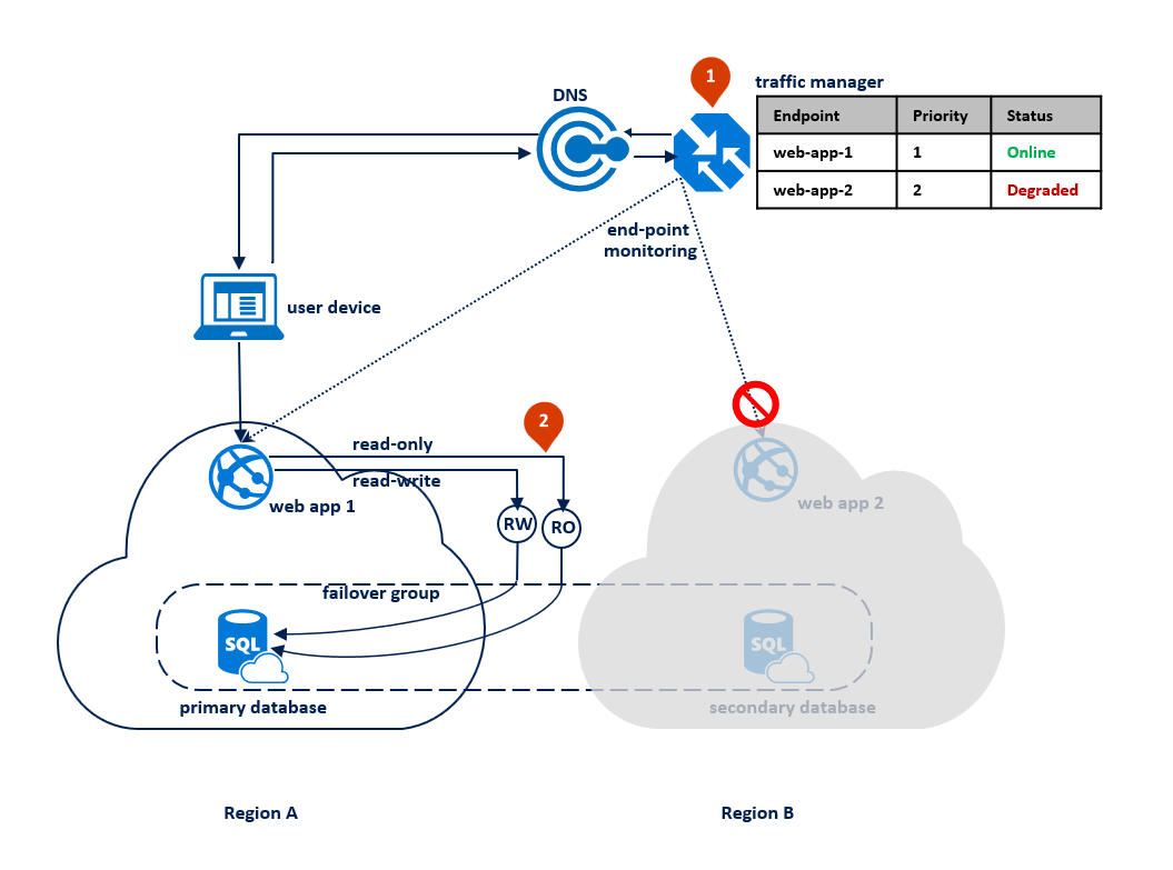
Once the outage is mitigated, the secondary database is immediately synchronized with the primary and the read-only listener is switched back to the secondary database in region B. During synchronization performance of the primary could be slightly impacted depending on the amount of data that needs to be synchronized.
This design pattern has several advantages:
- It avoids data loss during the temporary outages.
- Downtime depends only on how quickly Traffic Manager detects the connectivity failure, which is configurable.
The tradeoff is that the application must be able to operate in read-only mode.
Business continuity planning: Choose an application design for cloud disaster recovery
Your specific cloud disaster recovery strategy can combine or extend these design patterns to best meet the needs of your application. As mentioned earlier, the strategy you choose is based on the SLA you want to offer to your customers and the application deployment topology. To help guide your decision, the following table compares the choices based on recovery point objective (RPO) and estimated recovery time (ERT).
| Pattern | RPO | ERT |
|---|---|---|
| Active-passive deployment for disaster recovery with co-located database access | Read-write access < 5 sec | Failure detection time + DNS TTL |
| Active-active deployment for application load balancing | Read-write access < 5 sec | Failure detection time + DNS TTL |
| Active-passive deployment for data preservation | Read-only access < 5 sec | Read-only access = 0 |
| Read-write access = zero | Read-write access = Failure detection time + grace period with data loss |
Next steps
- For a business continuity overview and scenarios, see Business continuity overview
- To learn about active geo-replication, see Active geo-replication.
- To learn about failover groups, see Failover groups.
- For information about active geo-replication with elastic pools, see Elastic pool disaster recovery strategies.
Feedback
Coming soon: Throughout 2024 we will be phasing out GitHub Issues as the feedback mechanism for content and replacing it with a new feedback system. For more information see: https://aka.ms/ContentUserFeedback.
Submit and view feedback for