Overview
.jpg)
Mission Creation
An ESP mission is a structured experience that can be an adventure, a tutorial, a test of knowledge or skill, a performance evaluation, or whatever the creator can dream up. Mission Creation is a fairly complex process involving many elements. The process is implemented using a powerful tool called the Object Placement Tool. Tutorial: Creating a Mission explains how to install the tool, how to create a simple mission using it, and how to add that mission so that it shows up in the simulation. These missions are stored in XML files and are made available to the user through the options described in the Solution Deployment section of the SDK Overview.
The Mission Object Reference section explains all the options available to make more complex and involved missions.
ESP offers a variety of mission types; see Sample Missions for a complete list. The Object Placement Tool is primarily designed to create the basic structure of a mission. Manually editing the XML mission code, or the development of proprietary tools, provides a broader range of possible mission variations. See Manual Editing of Mission Files for more details.
See Also
Table of Contents
Setup
- Testing for a successful setup
Tutorial: Creating a Mission
- Step 1: Design the Mission
- Step 2: Create the Mission Metadata
- Creating New Categories
- Step 3: Link the Mission to a Flight File
- Step 4: Test for successful creation of the Mission
- Step 5: Record the Audio for the Mission
- Step 6: Introduce the Mission to the User
- Step 7: Add a Property Trigger, or two
- Step 8: Add a Proximity Trigger
- Step 9: Add an Object Activation Action
- Step 10: Add an Airport Landing Trigger
- Step 11: Add Goals and Rewards
- Creating Rewards
- Step 12: Test and Refine the Mission
- Creating an SPB file
Hints and Tips using the Object Placement Tool
Mission Object Reference
Mission File Structure
Actions
- Generic Action Properties
- Activate Waypoints Action
- Adjust Payload Action
- Attach Droppable Payload Action
- Attach Effect Action
- Change Object Type Action
- Count Action
- Custom Action
- Dialog Action
- Disqualify Player Action
- Failure Action
- Goal Resolution Action
- Grant Reward Action
- Object Activation Action
- One Shot Sound Action
- Play Animation Action
- Play Flight Recording Action
- Play List Action
- Point Of Interest Activation Action
- Random Action
- Race Course Start Action
- Race Course Activate Action
- Refill Action
- ResetTimer Action
- Rumble Action
- Spawn Action
- Time Penalty Action
- Timer Adjust Action
AI Objects
- AircraftAI Object
- TakeoffAI Object
- LandingAI Object
- TaxiAI Object
- GroundVehicleAI Object
- Waypoint List Object
- Waypoint Object
Area Definition Object
Group Object
Mission Objects
Allowable Container List
Camera
- Attached World Position
- Attached World Object
Condition Race Point
Gate Race Point
Living World Exclusion
Picture In Picture View Controller
Player
Point Of Interest
Pylon Race Point
Race Course
Race Info
Realism Overrides
Ridge Lift
Scenario Metadata
Thermal
Volume Race Point
Scenery Objects
Mobile Scenery Objects
Spawn List
Triggers
- Generic Trigger Properties
- Airport Landing Trigger
- Area Landing Trigger
- Collision Trigger
- Counter Trigger
- Last Lap Trigger
- Menu Prompt Trigger
- Parking Trigger
- Property Trigger
- Proximity Trigger
- Race End Trigger
- Timer Trigger
Goal Object
Disabled Traffic Airport Object
Sample Missions
Manual Editing of Mission Files
- Complex Condition Statements
- Testing that an Object Exists
- Starting AIPlayback
- Incorrect Type Entry
Setup
The Object Placement Tool is coded in Object_Placement.dll. Object_Placement.dll can be found in the Microsoft ESP\1.0\SDK\Mission Creation Kit directory. To install a new library first locate the dll.xml file. On Windows XP this should be in the C:\Documents and Settings\<user name>\Application Data\Microsoft\ESP folder. For Windows Vista the file should be in the C:\Users\<user name>\AppData\Roaming\Microsoft\ESP folder. The dll.xml file defines all the libraries that are to be loaded along with the simulation, not just the one for mission creation.
If the dll.xml file already exists in this folder, check it contains the following lines that are in bold -- and ensure that the Disabled parameter is set to False. If the file exists, but no reference is made to the Object_Placement.dll, then add the bold lines to the file. If the dll.xml file does not already exist in the right folder, then copy the dll.xml from the Mission Creation Kit folder over to the folder mentioned above.
| <?xml version="1.0" encoding="Windows-1252"?> <SimBase.Document Type="Launch" version="1,0"> <Descr>Launch</Descr> <Filename>dll.xml</Filename> <Disabled>False</Disabled> <ManualLoad>False</ManualLoad> <Launch.Addon> <Name>Object Placement Tool </Name> <Disabled>False</Disabled> <ManualLoad>False</ManualLoad> <Path>SDK\Mission Creation Kit\Object_Placement.dll</Path> </Launch.Addon> </SimBase.Document> |
Note that the Path parameter is either absolute, or relative to the installation Microsoft ESP/1.0/ folder. The path given above might change if the SDK or ESP were not installed to their default folders. If there are other add-ons that need to be loaded in addition to the Object Placement Tool, such as the Special Effect Tool, then they will also need Launch.Addon entries.
This is all the setup that is necessary.
Testing for a Successful Setup
You will know that the tool has been correctly installed when you start up ESP. Do this from the command line prompt: ESP -dev, as this will ensure that you are in dev mode while developing missions (so the menu options you will need are available). Refer to the Solution Deployment section of the SDK Overview for more details.
First, there will be a diagnostic window for SimConnect that should report that the dll has been launched. Second, the tool will be available in the Tools menu of ESP.
Ensure that ESP is running in Windows mode and not full-screen mode (you can toggle between these modes by pressing ALT+ENTER).
If you get an error message in the SimConnect diagnostic window, check the SimConnect.xml file for the correct path to the tool, and check that the tool is where it should be.
If the tool has been installed correctly, clicking on Object Placement in the Tools menu will give you the dialog below:
.jpg)
Recommendation
Because of the size of the dialogs, it can be easier to create missions using dual screens: one containing the tool dialogs, and the other showing the terrain where the Mission objects are being placed. If you are using a single small monitor, you will have to keep moving the tool dialogs out of the way to correctly position your objects.
Close ESP for now. The first step in creating a mission is done outside of the program.
Tutorial: Creating a Mission
This section details all the steps necessary to create a simple mission involving a takeoff, a single task, and a successful landing.
Step 1: Design the Mission
For experienced mission designers, it is a very good idea to design the mission in some detail before starting to use the tool to create it. However, for those new to using the tool, it is easier to simply start with a basic outline. For this tutorial, the outline of our mission is:
- Fly a Cessna out of Boeing Field
- Reach a certain altitude and speed (1000 feet and 80 knots)
- Complete a left or right traffic pattern
- Land back at Boeing Field, trying to land on the runway number
- When the aircraft has landed, the mission is over
The next stage is to do a bit of preparatory work before working the tool. ESP loads up the missions that are in the Microsoft ESP/1.0/Missions directory, so start by adding a subdirectory to this called Missions in Progress, and a subdirectory to this called Creation Tutorial.
Now add three files to the Creation Tutorial directory: two image files and one HTML briefing file. The two image files should be square and will appear in the Missions list of ESP. The first will appear before the mission has been completed by the user, and the second when the mission has been completed. The images should be 380 pixels wide x 232 pixels in height and either 256 color or 5-6-5 format (use the Imagetool utility to convert 24-bit bmp files to 5-6-5 format). The image should give some idea of what the mission is about. For our tutorial, we will use a picture of a Cessna:
.jpg)
The briefing file should be an HTML file describing the mission. You will probably not be able to complete the briefing file until the final mission is completed and tested, but for now, use one of the images and our mission description. For example:
Mission Creation Tutorial
|
Fly a Cessna out of Boeing Field, reach a certain altitude and speed (1000 feet and 80 knots), and then land back at Boeing Field. |
In summary, the Creation Tutorial directory now contains three files:
- Cessna_Complete.jpg
- Cessna_Incomplete.jpg
- MissionCreationTutorial.HTML
Step 2: Create the Mission Metadata
The next step is to create metadata for the mission. Some of this information is just for your own use in organizing and retrieving the missions that you are working on. Start up ESP again, and select the Cessna C172P Skyhawk, and for airport, select Boeing Field King Co Intl. Then click on the Object Placement Tool from the Tools menu.
In the main Mission tab, first click New Mission, and then enter a suitable name and description such as Mission Creation Tutorial, and some appropriate text for the description. These do not appear when the mission is being run but are for your own use in cataloging and maintaining your own missions. Next, click on the Objects tab. This will bring up the following screen:
.jpg)
Click on the Add button, and then in the first drop-down list box (activated by clicking within the box), select MissionObject. Click in the second box to display the drop-down list of mission objects, and then select ScenarioMetadata. Click on Add again, and the dialog should look like this:
.jpg)
Note
If you get the error message "You need to be looking at or closer to the ground," use the hat switch on the joystick to lower the green crosshairs so that they point at the ground. This can be necessary even though the object being entered is not relevant to any particular ground location.
The next step is to add the appropriate values for the properties of the metadata. To edit any value, double-click the entry in the Value box. For this mission, enter Mission into ScenarioType, Seattle into LocationDesc, select Beginner for skill level, and enter 15 minutes for EstimatedTime. The DifficultyLevel can be any integer value and is used to sort the list of missions by difficulty, with the easiest appearing first. For the sake of convenience, leave this at 0 so that the mission appears at the top of the list each time you start ESP. When you have completed creating the mission, if it is to be used by others, compare the difficulty (and the DifficultyLevel value) with other missions and then change this to an appropriate value.
UncompletedImage refers to the bitmap that is to be displayed before the mission has been completed by the user, so type Cessna_Incomplete.jpg here. Obviously, the CompletedImage refers to the bitmap that will be used when the mission has been completed, so type Cessna_Complete.jpg. For MissionBrief, type MissionCreationTutorial.HTML.
Leave the text messages and CategoryRef unchanged for now.
Note
It is important to not add a filename to the metadata until that file actually exists, otherwise the tool may crash. This is why we created the briefing file and images first.
Now save off the mission by going back to the Mission tab and clicking Save Mission. The default is to save the mission file into your My Documents\ESP Files directory, but instead, navigate to the Microsoft ESP\1.0\missions\Missions in Progress\Creation Tutorial directory, and save the mission there with the filename MissionCreationTutorial. Saving a mission will write out the details of the mission to an XML file. If you open up the file that has just been saved, it should look similar to this:
Now is a good time to enter the category of your mission. The category (referenced by a GUID in the CategoryRef property of the metadata) will identify the mission as one from the following list:
- Tutorials
- Just for Fun
- The Good Life
- Backcountry
- Pilot for Hire
- Emergency
- Airline Pilot
- Challenges
- Military
- Test Pilot
- Racing
To set the category GUID in your metadata, cut and paste the value out of this Category file. We will use the Tutorial category for this mission. Typically, a tool such as Notepad is used to make this kind of edit to the mission data. Make sure to include the brackets {} when you cut and paste the GUID.
Creating New Categories
It is possible to make your own categories. To do this, create a new XML file and add the appropriate text and GUID entries to it. The file should be placed in the Microsoft ESP/1.0/Categories folder. ESP will open and read all XML files in this folder (not any subfolders, though), and read all SimMissionUI.ScenarioCategory entries. Care should be taken to save off the file in Unicode (not ANSI) and to name the new XML file appropriately so that it will not be identical to any other third-party category file (use your company name, a GUID, or some other reliable file naming convention). Do not update the FSCategories.XML file, as this data can be lost when updates to ESP are installed.
Refer to the Hints and Tips section of the SDK Overview documentation for information on how to generate your own GUIDs. The format of a new categories file follows; add as many <SimMissionUI.ScenarioCategory> elements as necessary (change the items in bold appropriately):
| <?xml version="1.0" encoding="UTF-16" ?> - <SimBase.Document Type="AceXML" version="1,0" id="FSCategories"> <Descr>AceXML Document</Descr> <Filename>YourFSCategories.xml</Filename> - <SimMissionUI.ScenarioCategory id="{GUID}"> <Descr>Description of your new category.</Descr> <Title>Title of your new category </Title> <PreviewImage>banner_image.bmp</PreviewImage> </SimMissionUI.ScenarioCategory> </SimBase.Document> |
The banner image should be 335 pixels wide x 75 pixels in height, and it, too, should be placed in the Microsoft ESP/1.0/categories folder.
References
Scenario metadata mission object
Step 3: Link the Mission to a Flight File
The next step is to link the mission we have just started to a flight file. It is flights that are loaded into ESP, not missions, so we need to attach the two. If you did not do so at the beginning of Step 2, set up the starting location within ESP -- that is, create a flight with your chosen aircraft at the chosen airport. For this sample mission, we are using a Cessna at Boeing Field airport.
Having placed your aircraft at the right location, select Save Flight from the Flights menu and save it off. Name the saved file MissionCreationTutorial. Now close ESP.
Next, go to the My Documents\ESP Files directory and cut and paste (or move) the flight file and weather file of the flight that you just saved over to the location where you saved the mission. In our example, the mission was saved to the Missions in Progress\Creation Tutorial directory, which, after moving the flight and weather files, should now contains six files:
- MissionCreationTutorial.xml
- MissionCreationTutorial.FLT
- MissionCreationTuturial.WX
- Cessna_Complete.jpg
- Cessna_Incomplete.jpg
- MissionCreationTutorial.HTML
In the Creation Tutorial folder, open up the flight file (MissionCreationTutorial.FLT) in Notepad.
The first section of a flight file should be [Main]. Under this should be Title= and Description=. This is the text that will appear as the title and description for the mission in the Flight/Load menu (along with the image file created earlier), so edit the text, perhaps adding spaces, so that it is as you want it to appear. For example:
[Main] Title=Mission Creation Tutorial Description=Takeoff and fly!
Now, go to the very end of the file and type the following section entry:
[ObjectFile] File=MissionCreationTutorial
Note that the XML file extension is not added to the filename, and that there are no spaces around the equals signs. This links the mission to the flight file.
Now save off the flight file.
Step 4: Test for Successful Creation of the Mission
The next step is simply to test what we have done so far. Start up ESP, select the Flight/Load menu, and check that the Mission Creation Tutorial has appeared with the correct image and text.
Select the mission. The first thing that should appear is the short briefing file we created. Start the mission, and you should be sitting on the runway in a Cessna at Boeing Field. If all is well, select End Flight. An End of Mission dialog should appear but without any goals or rewards, as we have not yet added any to our mission.
If all this appears correctly, then the first steps are complete; if not, examine the XML and flight files to check for mistakes.
Step 5: Record the Audio for the Mission
You can, of course, record the audio for your mission at any time, but as you are going to start adding dialog and other actions to the mission, now might be a good time to do it. Each piece of spoken text -- by a co-pilot, ATC, instructor, passenger, or whomever -- should be recorded, probably in mono. Also, any special sound effects should be created, too; these could be in mono or stereo sound as appropriate.
Most sound files should be created as 22KHz mono wave (.wav) files. There is no point sampling at a higher rate, as the sound engine will down-sample any such files to 22KHz. An option is MS-ADPCM compression, but it is not required. Audio content tends to sound better uncompressed, but this will use up about four times the storage space as compressed audio.
You will probably have to revisit your sound recordings during the testing of your mission, but having the recordings handy now will increase the value of that testing.
Create a subdirectory of your mission directory called sound, and move all the recordings into this directory.
For our mission, add the following recordings to the sound directory:
- Mission1.wav: "Welcome to Boeing Field. Takeoff when you are ready."
- Mission2.wav: "Good, now climb to an altitude of 1000 feet with a speed of at least 80 knots."
- Mission3.wav: "Great, now complete a left or right traffic pattern and land back at Boeing Field. Try to land on the runway number."
- Mission4.wav: "Nicely done, now bring the aircraft to a complete stop."
- Mission5.wav: "Good job! You have completed the mission."
Of course, a real mission will have many more recordings, including good advice for when the participant is not doing so well.
Note
The audio engine does not support pre-rendered 5.1 surround sound (six channel wave files), but will render mono sounds (not stereo) in the correct 3D location, and will render in 5.1 surround sound if such a system is installed. However this does not apply to sounds recorded for missions, so mission audio is limited to mono and stereo.
Step 6: Introduce the Mission to the User
Ensure you have ESP up and running. First click Settings, then General, then select the Show Captioning check box, as shown below. This will ensure that you can both see the dialog text as well as hear the sound file. By default, the Show Captioning check box is left unchecked.
.jpg)
When you have done this, make sure the Allow realism changes during Missions check box is selected. This will make adding triggers and actions easier. Now click the Mission Creation Tutorial in the list of Missions, and then click Go To Briefing. When the briefing document appears start flying, and then open up the Object Placement Tool.
Most missions begin by introducing the mission to the user with some speech and text. The text will appear on the screen at the same time as the text is being rendered by the audio system. The first step is to add the dialog actions. Do this by clicking Add, selecting Action in the First box, then DialogAction in the Second box, and then entering the Text and SoundFileName properties as appropriate:
.jpg)
Repeat this process of adding Dialog actions for all five recordings you have made for this mission. In each case you should only be typing into the Text and SoundFileName properties. Notice how each action is appended with a number in the All Items list.
The next step is to add a timer trigger, which will initiate the first of our dialog actions.
To do this go to the Object tab of the tool, click Add, then select Trigger from the First box, and TimerTrigger from the Second box. Click Add again and you will see the list of properties associated with a timer trigger:
.jpg)
It is best to let the user wait a few seconds before introducing the mission to the user, so change the StopTime value to 5.0. Leave the StartTime at 0.0, so the timer starts when the flight is loaded. Actions are initiated by timer triggers when the stop time is reached, so these two values will initiate the text and speech 5 seconds into the mission.
The property OneShot set to True simply means that the action should only be fired once (this is not very important for timer triggers, which are only fired once, but you will have to decide with other triggers whether you want them to keep firing their actions if a user keeps triggering them). Activated should be True -- this means that this trigger is to be considered active, and is not waiting for any other event before it is to become active. Leave the other properties as they are.
Note
The All Items box, in the top right corner of the dialog, now contains the additional item we have added. Clicking on any item in this box will bring up that item and its properties to the boxes below.
We have not finished yet, as we have not yet linked the timer trigger and the dialog action. Do this by clicking on Property Set for the Actions property. This will bring up a list of items in the Elements box that this trigger could be linked to. Double-click on DialogAction1 in the Elements box to link the trigger and action. This will be shown both by a + sign appended to the name in the Elements box, and also an entry in the References box, as shown below:
.jpg)
This is all we need to do to introduce our mission.
Go back to the Missions tab and save off the mission. Then exit the flight, start the mission again, wait five seconds, and you should both see and hear the text Welcome to Boeing Field. Takeoff when you are ready. If you do, then all is well, if not, go back and check the properties for the trigger and action.
This is one of the most simple examples of a trigger and action, but this process of linking these two elements of a mission applies throughout the tool.
Notes
The Latched property appears in all the triggers, but this is not a value that is set when creating a mission. Latched will be set to True when a trigger fires, so if a mission is saved off part way through, and reloaded later, the system will have recorded where the user is within the mission.
Actions in a mission are queued up one after another as they are fired. Dialog actions do not pass processing to the next action until the attached wave file (if there is one) has completed playing. There can also be an additional delay added to the end of a dialog action by entering a value into the DelaySeconds property for the action. This is to ensure the user both has time to read the text and/or hear the wave file, but also extra time to respond to any request that this speech has made, as the next action may well be testing for that response.
References
Dialog actions
Timer triggers
Step 7: Add a Property Trigger, or Two
If it is not still loaded, reload the mission and open up the Object Placement Tool.
All our mission does so far is ask the user to takeoff. To give them the next stage in the mission, we can give them some more details just after the aircraft has taken off. To do this we can use a property trigger and link it to our second dialog action.
Click Add, then select Trigger and PropertyTrigger. A property trigger is one that tests one or more conditions, typically speed or altitude of the aircraft, but there are many hundreds of other possibilities.
In the Properties box of the property trigger, ensure Activated is True, and click on the Property Set for Actions. Then double-click on DialogAction2 (in the Elements list) to link it to the property trigger. Then double-click on the Property Set for the Condition property. This will bring up the Conditional Editor dialog box. Click Add Term and select Simvar.AltitudeAMSL for the left hand side of the condition (LHS). Leave the Operator as Greater Than, and type 50.0 for the right hand side (RHS), so the dialog looks like this:
.jpg)
The simple condition we have entered indicates that the trigger will be fired when the user's aircraft is more than 50 feet above ground level. The units of a condition appear under the Simvar property. If the unit of measurement for any simulation variable is not obvious, refer to the Simulation Variables document. Click OK to add the condition to the trigger.
Notes
Both the left and right hand sides of a condition can be one of: Property, Double, Long, Unsigned, Boolean or String. If Property is selected the next box will by default contain [User]. [User] refers to the user's aircraft, obviously, but there can be other aircraft under control of the AI component of ESP, and if these aircraft existed property triggers could be set on them too.
There is an issue with the Object Placement Tool that some options are presented that simply do not apply given the selections that have been made. This applies both in the main dialog and the Conditional Editor. Mission designers should study the Mission Object Reference, and be prepared for some trial and error, in the creation of missions using this tool.
For reference, the PropertyTrigger2 properties should now look like this: .jpg)
In our sample mission we want the user to fly up to an altitude of 1000 feet, with a minimum speed of 80 knots, before returning. To do this we should now enter a second property trigger, this time with two conditions, and of course a link to the third speech dialog to indicate when this has been done.
Enter two conditions into the property editor:
- Simvar.AltitudeAMSL Greater Than 1000.0
- Simvar.IndicatedAirspeed Greater Than 80.0
And click on the Actions Property Set to link to DialogAction3.
Notes
In the first property trigger the AltitudeAGL (above ground level) value is used, to ensure that the aircraft has taken off, but in the second property trigger AltitudeAMSL (above mean sea level) is more appropriate.
With multiple conditions usually they will all have to be true for the trigger to fire, so the default is for conditions to be ANDed together. Set the Term list operator box value to OR if only one condition has to be true to fire the trigger. Note that conditions involving both OR and AND logical operators cannot be created using the Condition Editor. It is easy to see how quite complex conditions could be entered as property triggers. They can test for both success and for troubling situations like excessive G forces, pitch angles, airspeed and so on.
If multiple conditions are entered each can be edited or deleted by selecting them in the condition box (which will have the number of the condition and the total number of conditions preceding it), such as:
.jpg)
Save off the mission, then restart it and test that both property trigger dialog actions are triggered at the appropriate points. Notice how simply climbing above 1000 feet does not fire the second property trigger, it is necessary to increase the speed to 80 knots before it does fire.
References
Property Trigger
Step 8: Add a Proximity Trigger
A proximity trigger will fire if the specified object (usually the user's aircraft) enters a specified box. The box is defined by a length, width and height, and can be placed anywhere in the world. It is usually most useful to move to the approximate location for the proximity trigger first. The joystick and hat switch can be used to move the crosshairs, you may also want to use the Slew feature to move larger distances. In our example we want to create a proximity trigger at the ideal landing spot on the runway (the runway number). First use the joystick to select the center of the runway number, then click Add and select AreaDefinition and RectangleArea. The length, width and height property values can be edited, so change them to a length and width of 100 (units are in meters), and a height of 20. .jpg)
The orientation about each axis can also be changed (though is not necessary in this case), and set the Rendered property to True if the box should actually appear in view. Set Rendered to be True for this sample.
The next step is to add the proximity trigger and attach it to this area definition. To do this select Add then select Trigger and ProximityTrigger, then in the Properties box click on Areas, then double-click RectangularArea1 in the Elements box. This links the trigger to the area. Also, select the OnEnterActions property and link it to DialogAction4, to link entering the area with the appropriate speech.
For this proximity trigger we do not want it to be activated until the user is airborne, and has completed the previous step (climbed to 1000ft with a speed of 80 knots), so we set the Activated property to False. The next step is to change the activated property to true, at the appropriate time.
Notes
When a mission is saved off, area definitions become locked, and the properties cannot be edited until the Locked box is unchecked. This is to help prevent accidental changes to a carefully placed area.
For future reference, more than one proximity trigger can be attached to a single area definition, and it is also possible to attach proximity triggers to moving objects. This is more advanced than we need for our first mission, but refer to the reference for more information on how to do these things.
Make sure you are saving off the mission regularly.
References
Area Definition object
Proximity Trigger
Step 9: Add an Object Activation Action
To link the inactive proximity trigger to the completion of a previous action, go through the following steps.
First, add an ObjectActivationAction to the mission. It only requires a few properties: leave NewObjectState as True, and click on ObjectReferenceList to display a list in the Elements box. Double-click on ProximityTrigger4. This means when the object activation action occurs it will activate the proximity trigger.
Next, select PropertyTrigger3 (with the altitude of 1000 feet and speed of 80 knots condition) from the All Items list, and click on Actions. Double-click on the ObjectActivationAction5 entry under Elements. PropertyTrigger3 now fires two actions, a dialog action and the object activation action.
The logic here should be fairly clear. The proximity trigger is inactive until the user's aircraft reaches the required altitude and speed. When the aircraft does meet these requirements the proximity trigger becomes active.
Note
A trigger can activate any number of actions.
References
Object activation action
Step 10: Add an Airport Landing Trigger
Many missions will end with a successful landing. Add an AirportLandingTrigger and enter the four digit Airport identification code to identify the correct airport (KSEA for Sea-Tac International or KBFI for Boeing Field, for example). Again set the Activated property to False. Set the Actions property to trigger DialogAction5, which is the appropriate mission completed text. For this case leave the landing as FullStop (the alternatives are TouchDown and Any), and leave the RunwayFilter entry for now (it is possible to specify which runway must be landed on to fire the trigger).
Go back to the ObjectActivationAction created in Step 9 (click on it in the All Items list) and add the AirportLandingTrigger to the actions that become active when the object activation action fires.
References
Airport landing trigger
Object activation action
Step 11: Add Goals and Rewards
For this mission we might decide that there are two goals, one for the user to enter the proximity trigger box and land on the painted runway number, and the second for a correct landing (coming to a complete stop).
Add goals by clicking Add, then selecting Goal. The goal state should be left as pending. The text entered here will appear in the End Mission dialog, along with the final state of the goal (pending, completed, or failed). Enter two goals, one for landing on the runway number, and another for a correct landing. The text can be Landed on the Painted Number , with an Order number of 1, for the first goal, and Complete Stop, with an Order number of 2, for the second goal.
Next, add a GoalResolutionAction for each goal. The Goals property of this action should be linked in the usual way to the goals themselves. Go to the ProximityTrigger and add the second goal resolution action (Landed on the Painted Number) to its list of actions. Finally go back to the AirportLandingTrigger and add the correct goal resolution action (Complete Stop) to the list of actions which it fires.
There is currently no concept of an optional goal in the Mission system.
Creating Rewards
Rewards are different from goals, they are persistent and added to the user's pilot records. A reward can be serious in the sense of a certificate for achieving some level of skill, or more trivial, for example a reward for photographing a humpback whale off Hawaii. The rewards that ship with ESP are integrated into the missions and tutorials that are provided, so it makes most sense to create your own rewards, if you choose to use them.
To create the simplest form of reward, go through the following steps:
- Create artwork for the reward. Use appropriate art tools to create one detailed piece of art for the reward (300 pixels wide x 370 pixels in height) and one thumbnail piece of art (100 pixels wide x 80 pixels in height). These will be referenced by the reward file and appear on the user's screen when aiming at and achieving the reward. The artwork can be .bmp or .jpg files.
- Fill out an XML file that matches the following format.
<?xml version="1.0" encoding="ISO-8859-1" ?> - <FSData version="9.0"> - <Reward rewardId="{GUID}" name="name of the reward" description="description of the reward." type="TROPHY" bitmap = "artwork_small.bmp" rewardDetailBitmap="artwork_large.bmp"> </Reward> </FSData> - Create and enter a GUID for the reward, to be referenced by the mission itself.
- Enter a name to appear in ESP.
- Enter a description to appear when the user selects View details.
- Enter a type for the reward, which can be one of: TROPHY, BADGE, MEDAL, CERTIFICATE, POSTCARD or SPECIAL_ITEM.
- Enter the filename for the thumbnail piece of art, and the detailed piece of art.
- Ensure that both pieces of art and the XML file are in the same folder, then run the command line tool, BGLComp with the XML file as input (entering the command: BGLComp reward.xml). Alternatively drag the reward XML file over the BGLComp icon. The BGLComp toolis in the Environment Kit\BGLComp SDK folder. This will create a rewards file, with a .rwd extension. Copy the rewards file to the Microsoft ESP/1.0/rewards folder. This file includes the artwork, so is the only file required.
- Add the reward to a mission by selecting its GUID in a Grant Reward action, and then link this action it to the final trigger.
A rewards file can contain any number of rewards, simply by entering as many <Reward> </Reward> entries in the XML file as there are rewards. More complex rewards can be created by adding a <Criteria> section to a reward. The following table shows an example with all the possible criteria.
| <! An example comment: hours include decimal places, 2.5 hours for example > <Criteria landings="2" differentAirports="2"> <RewardHours hours="10" hoursType="ANY" /> <RewardHours hours="10" hoursType="DAY" /> <RewardHours hours="10" hoursType="NIGHT" /> <RewardHours hours="10" hoursType="VFR" /> <RewardHours hours="10" hoursType="IFR" /> <RewardHours hours="10" hoursType="SAILPLANE" /> <RewardHours hours="10" hoursType="LANDPLANE" /> <RewardHours hours="10" hoursType="SEAPLANE" /> <RewardHours hours="10" hoursType="ROTORCRAFT" /> <RewardHours hours="10" hoursType="MULTI_ENGINE" /> <RewardAirport ident="KORD" /> <RewardAirport ident="KSEA" /> <RewardAirport ident="KBFI" /> <DependantRewardId rewardId="{GUID}" /> <DependantRewardId rewardId="{GUID}" /> </Criteria> |
The criteria in the above example are not very realistic, they require the user to have completed two landings at two different airports and landed at the list of the three specified (KORD, KSEA, and KBFI). It also requires 10 hours experience in a whole range of situations, and that two other rewards must have been earned before this one can be given. All criteria are logically ANDed to make up the requirement for a reward, and all equals signs should be interpreted as greater than or equal to (in other words, at least 10 hours experience in all the aircraft and situations listed in the example above). The following table gives some more realistic examples:
| - <Reward rewardId="{GUID}" name="10 hours flying " description="Earn a medal for flying any aircraft for a total of 10 hours flying time." type="MEDAL" bitmap="small.jpg" rewardDetailBitmap="large.jpg"> - <Criteria> <RewardHours hours="10" hoursType="ANY" /> </Criteria> </Reward> |
| - <Reward rewardId="{GUID}" name="15 hours at night " description="Earn a certificate for flying any aircraft for a total of 15 hours flying at night." type="CERTIFICATE" bitmap="small.jpg" rewardDetailBitmap="large.jpg"> - <Criteria> <RewardHours hours="15" hoursType="NIGHT" /> </Criteria> </Reward> |
| - <Reward rewardId="{GUID}" name="25 landings" description="Earn a badge for completing 25 landings." type="BADGE" bitmap="small.jpg" rewardDetailBitmap="large.jpg"> <Criteria landings="25" /> </Reward> |
| - <Reward rewardId="{GUID}" name="Remote location" description="Earn a postcard for landing on Easter Island." type="POSTCARD" bitmap="small.jpg" rewardDetailBitmap="large.jpg"> - <Criteria> <RewardAirport ident="SCIP" /> </Criteria> </Reward> |
| - <Reward rewardId="{GUID}" name="Busy airports " description="Earn a trophy for landing at 3 of the busiest airports in the world: London Heathrow, Atlanta and Singapore." type="TROPHY" bitmap="small.jpg" rewardDetailBitmap="large.jpg"> - <Criteria> <RewardAirport ident="EGLL" /> <RewardAirport ident="KATL" /> <RewardAirport ident="WSSS" /> </Criteria> </Reward> |
References
Goal objects
Goal resolution action
Grant Reward action
Step 12: Test and Refine the Mission
Having completed building the mission, ensure you have saved it all off, and then test it thoroughly. The best designed mission can still exhibit strange behavior during testing.
There are of course many cases where the mission might inappropriately reward a user. For example, the proximity trigger in our example will still fire correctly if the aircraft is landing upside down, without its gear down, too fast, or whatever. To tighten up a mission you will need to add conditions to many of the triggers, especially the proximity triggers.
This ends the tutorial section of this document. The most popular and useful actions and triggers are covered in the tutorial, but there are many others, and the following reference section describes all the Mission Objects.
You can also refer to the missions provided with ESP (by loading them into the Object Placement Tool, or viewing the XML in an appropriate editor) for examples of how different triggers, actions, goals and rewards can be used. Mission files created using this tool are in an open XML format. Mission files supplied with ESP are in a binary format with the .SPB extension. To help in the understanding of the mission system, the XML files used to create the Sample Missions are supplied in a subfolder of this SDK.
Creating an SPB file
Mission files can either be in XML or SPB (Sim-Prop Binary) format. See the section Creating an SPB File in the Creating XML Gauges document for details on how to use the simpropcompiler tool.
Error Reports
To get more detailed error reports when there is an error in a mission file, make sure the following entry is in the ESP.cfg file, which is in the Documents and Settings\<username>\Application Data\Microsoft\ESP folder.
[DEBUG] ReportLoadErrors=1
Hints and Tips using the Object Placement Tool
This section describes a few techniques that mission designers should find helpful when using the Object Placement Tool. Also, some very helpful information is available at Mission Building Tips.
Selecting an Object
To place an object using the mouse, first double-click on the Value entry of the World Position property, and then click on the desired location in the 3D view. This will place, or move, the object to that location. In the image below an Area Definition object is being placed as part of a taxiing route.
 |
Rotating an Object
To rotate an object using the mouse, first double-click on the first or last of the three Value entries of the Orientation property. To rotate around the X axis, double-click on the first Orientation value, then move the mouse up or down. To rotate around the vertical Y axis, double-click on the third value and move the mouse left or right. There is no mouse control over rotation in the Z axis (these should be entered by hand into the Orientation property). The image below shows a car being rotated into position.
.jpg) |
Completing Triggers
It is good practice to complete the entry of triggers before loading a mission into the simulator. For example, the OnEnterCondition should be entered, and an appropriate action referenced. Triggers that are not complete in this way can lead to unexpected behavior during testing with the simulator.
Mission Object Reference
This section reference information for mission designers, including the file structure to follow, and of all the properties that apply to each of the Mission Objects. For examples of the use of these objects, refer to Sample Missions.
- Mission File Structure
- Actions
- AI Objects
- Area Definition Objects
- Group Objects
- Mission Objects
- Scenery Objects
- Mobile Scenery Objects
- Spawn Lists
- Triggers
- Goal Object
- Disabled Traffic Airport Object
Mission File Structure
The missions that you create should be placed under the ESP\Missions\ folder, and follow the same folder structure as the sample missions provided -- with the briefing file, and other files referenced by the mission, in the same directory as the mission XML or SPB file, and the audio in a \Sound sub-folder. These files can reference other files, such as the images in the Common folder, for example, but should not reference files outside of the ESP\Missions folder.
Actions
An action is a declarative way to cause something to happen in the world. Examples of actions are playing a sound file, completing an objective, showing text in the adventure window, failing an engine, completing a goal, etc.
In multiplayer mode, actions with the TargetPlayer property will affect the players specified by the property. If an action does not contain this property the action will affect only the local player, with the exception of Race Course Start Action and Race Course Activate Action, which affect all players.
- Generic Action Properties
- Activate Waypoints Action
- Adjust Payload Action
- Attach Droppable Payload Action
- Attach Effect Action
- Change Object Type Action
- Count Action
- Custom Action
- Dialog Action
- Disqualify Player Action
- Failure Action
- Goal Resolution Action
- Grant Reward Action
- Object Activation Action
- One Shot Sound Action
- Play Animation Action
- Play Flight Recording Action
- Play List Action
- Point Of Interest Activation Action
- Random Action
- Race Course Start Action
- Race Course Activate Action
- Refill Action
- ResetTimer Action
- Rumble Action
- Spawn Action
- Time Penalty Action
- Timer Adjust Action
Generic Action Properties
All actions include the following properties.
| Property | Description |
| id | Reserved. Do not edit this field. |
| Descr | The name of the action. The system will generate a name such as DialogAction1, simply by appending the number of the next action to the type of action. This name can be edited to help identify it further, though it is a good idea to maintain the type of action in the name, as this information is not clearly available through any other mechanism. Make sure though that the name is unique. |
| InstanceId | This is the GUID generated to ensure the object has a unique reference. Do not edit this field |
Activate Waypoints Action
Waypoints are essential for the movement of certain AI objects. The activate waypoints action provides one or more AI object with a new list of waypoints.
| Property | Description |
| Generic Action Properties | See description above. |
| ObjectReference |
List of one or more AI objects that are to use the new waypoint list. |
| WaypointList |
List of one or more waypoints that are to become active. |
Adjust Payload Action
An adjust payload action is used to set, or add to, the weight on a payload station.
| Property | Description |
| Generic Action Properties | See description above. |
| ObjectReference |
The list of objects to which the payload adjustment applies. |
| StationIndex |
The index number of the station. |
| AdjustmentType |
One of: Set or Add. |
| Weight | The quantity of the adjustment. |
| Units | One of: number, feet, g_force, knots, pounds, percent, boolean, degrees or radians. |
Attach Droppable Payload Action
An attach droppable payload action is used to change the payload that gets dropped when the user presses a key configured to drop the payload.
| Property | Description |
| Generic Action Properties | See description above. |
| PayloadName |
The name of the container that becomes the object to be dropped. |
| PayloadCount |
The number of payload objects that should be attached. |
| ObjectReferenceList |
The objects which are each to get the assigned payload. |
Attach Effect Action
The attach effect action attaches a single special effect (such as smoke, fire, contrail etc.) to one or more objects.
| Property | Description |
| Generic Action Properties | See description above. |
| EffectName |
Filename of the special effect. The effect should be in the ESP/effects folder. |
| AttachPointName |
The name of the attach point (physical location) of where the effect is to be applied. See the Using Modeling Tools documentation and the Library Objects table for information on attach points. |
| ObjectReferenceList |
List of objects that the effect applies to. |
Change Object Type Action
A change object type action changes the object the user is in. For example, it can be used to change from one type of aircraft to another.
Note
Using this action with landing triggers is no longer allowed, as it can cause serious problems with multi-player races. If this functionality is required, the landing should activate a one second timer trigger which in turn fires the change object type action.
| Property | Description |
| Generic Action Properties | See description above. |
| ObjectType |
The identifying title of the new object, from an aircraft.configuration file. |
Count Action
A count action will add the value of the Count property to the Counter value in the given list of triggers (which should all be Counter triggers). Counter triggers will fire when a certain specified count is reached.
| Property | Description |
| Generic Action Properties | See description above. |
| Count |
Value to be added to the Counter triggers current counter. The default is 1. |
| Triggers |
List of Counter triggers to have their counts incremented. Note that these must be counter triggers, even though the Object Placement Tool lists other trigger types. |
Custom Action
A custom action is used to enable communications between a mission and a SimConnect client application.
| Property | Description |
| Generic Action Properties | See description above. |
| PayloadString |
Text that will be transmitted to the SimConnect client when the action is initiated. The text can be any string that the client might find useful. |
| WaitForCompletion |
Set this to True if a completion message must be received from the SimConnect client, before the mission progresses. Set to False otherwise. |
Dialog Action
A dialog action is used to add speech to be rendered over the audio system, and/or text to be displayed on the screen. See the explanation in the tutorial for more examples.
| Property | Description |
| Generic Action Properties | See description above. |
| Text | The text to appear on the screen. Can be left blank. |
| SoundFileName | The wave file to be rendered by the audio system. The file should be in the \sounds directory of the mission. Can be left blank. |
| DelaySeconds | A delay in seconds after the text and audio are rendered. Can be used to allow time for the user to respond to the dialog, before performing another action. |
| TargetPlayer | The players who should receive the dialog. One of: Local Player, All Players, Triggering Player, All but Triggering Player. |
Disqualify Player Action
A disqualify player action is used to disqualify and remove usually one player from a race.
| Property | Description |
| Generic Action Properties | See description above. |
| TargetPlayer | The players who should be disqualified. One of: Local Player, All Players, Triggering Player, All but Triggering Player. |
| Text | Text displayed to the disqualified players. |
Failure Action
A failure action is used to change the behavior of one of the aircraft's systems. It is possible also to change a failing system's status back to fully functional, by changing its HealthPercent value to 100. Failures only apply to the user aircraft, unless the TargetPlayer property specifies otherwise.
| Property | Description |
| Generic Action Properties | See description above. |
| System |
One of: (Engines and systems) Engine, EngineFire, Coolant, OilSystem, OilLeak, VacuumSystem, Pitot, Static, ElectricalSystem, Generator, FuelPump, FuelLeak, APU, APUFire, TurbineIgnition, HydraulicPump, HydraulicLeak, LeftMagneto, RightMagneto (Control surfaces and structural) Elevator, LeftAileron, RightAileron, Rudder, RearTail, LeftFlap, RightFlap, LeftWing, LeftWingTip, RightWing, RightWingTip (Landing gear) CenterGear, RightGear, LeftGear, AuxGear, LeftBrake, RightBrake, BrakeSystemHydraulicSource (Instruments) AltitudeIndicator, AirspeedIndicator, Altimeter, DirectionalGyro, Compass, TurnCoordinator, VSI (Radios) ComRadios, NavRadios, ADFRadios, Transponder |
| SystemIndex |
If an aircraft has multiple systems (usually applies to engines or instruments), enter the index of the system that the failure should apply to. |
| Behavior | Not implemented, use the HealthPercent property. |
| HealthPercent | Enter a value of between 0 (complete failure) and 100 (fully functional). For System entries such as OilLeak or FuelLeak the lower the HealthPercent the greater the leak. For control surfaces such as LeftWingTip the HealthPercent determines the lift. For instruments and radios no partial or intermittent behavior is implemented, so set the HealthPercent to 0 for not operational, or 100 for fully operational. |
| TargetPlayer | The players who should experience the failure. One of: Local Player, All Players, Triggering Player, All but Triggering Player. |
Goal Resolution Action
The goal resolution action is used to set whether goals have been completed or not. See the explanation in the tutorial for more examples.
| Property | Description |
| Generic Action Properties | See description above. |
| GoalResolution |
Set to completed or failed. |
| Goals |
List of Goal Objects to have their resolution changed. |
Grant Reward Action
The grant reward action rewards the user with a single reward, to be placed in their pilot records. See Creating Rewards for more details.
| Property | Description |
| Generic Action Properties | See description above. |
| RewardRef |
GUID of the appropriate reward. |
Object Activation Action
The object activation action will change the state of most different types of object, Triggers, AI objects, Scenery objects and some Mission objects. Do not use it for points of interest, use PointOfInterestActivationAction for that particular case.
| Property | Description |
| Generic Action Properties | See description above. |
| NewObjectState |
Set to True or False. |
| ObjectReferenceList |
List of objects (AI Object, Scenery, Mission Objects and Triggers) to have their status changed. |
| TargetPlayer | The players who should experience the object activation. One of: Local Player, All Players, Triggering Player, All but Triggering Player. |
One Shot Sound Action
The one shot sound action will render a single wave file. Use this for sound effects rather than dialog (use the Dialog action for speech audio).
| Property | Description |
| Generic Action Properties | See description above. |
| SoundFileName |
The wave file to be rendered. The file should be in the \sounds directory of the mission. |
Play Animation Action
The play animation action will initiate an animation sequence on one or more objects.
| Property | Description |
| Generic Action Properties | See description above. |
| AnimationGUID |
GUID of the animation. Refer to the section on Creating a New Animation in the Using Modeling Toolsdocument, which describes animation GUIDs. |
| LoopAnimation |
Set to True to loop the animation. |
| ObjectReferenceList |
The list of objects that the animation is to apply to. |
| TargetPlayer | The players who should experience the animation. Note that the animation may not apply to the user aircraft, but is specified in the ObjectReferenceList. One of: Local Player, All Players, Triggering Player, All but Triggering Player. |
Play Flight Recording Action
A play flight recording action is used to add a prerecorded flight to a mission, usually a multi-player racing mission. As the AI pilot in ESP is geared towards commercial and general aviation traffic, and not racing, an additional method of adding an aircraft to a race course is to record an aircraft (under user control) taking part on the race course, and then replaying that flight file during the actual race. Refer also to the AirplanePlayback property of AI objects.
Recording flight video during missions is disabled by default, in order to turn it on, enter the following line in the [USERINTERFACE] section of the ESP.cfg file:
AllowFlightVideoInMissions=1
| Property | Description |
| Generic Action Properties | See description above. |
| Filename | The filename of the recorded flight file (with an .FSR extension), that should be placed in the mission's specific folder (the same folder that contains the mission XML or SPB file). |
| ObjectReference | The AI object that should fly the recorded path. |
Play List Action
The play list action will play the specified music items on the adventure music track. Individual play list items can be set to a random position within the play list.
| Property | Description |
| Generic Action Properties | See description above. |
| PlayListItem |
Play list item object. To enter a play list, double-click on the PlayListItem Property Set, this will bring up an Objects dialog and select New, Insert Before or Insert After to add items to the list. Click OK when there are enough items in the list. This list will then appear in the Property Sets box of the Objects tab. Clicking on any one of these items will bring up the properties for each item. |
PlayList Item Object
A playlist item is an audio track that forms part of a playlist action.
| Property | Description |
| id |
Reserved. Do not edit this property. |
| Descr |
The name of the item. The system will generate a name such as PlayListItem1. This name can be edited to help identify it further. Make sure though that the name is unique. |
| SoundFileName |
The name of the wave file (typically music track) to be played. |
| RandomizeInList |
Set to True to randomize the playing of this particular track in the playlist. |
Point Of Interest Activation Action
A point of interest activation action will change the state of one or more Point of Interest objects. It is very similar to ObjectActivationAction, but also sets the current point of interest to be the one with the lowest cycle order in its list.
| Property | Description |
| Generic Action Properties | See description above. |
| NewObjectState |
Set to True or False. |
| ObjectReferenceList |
List of one or more Point of Interest objects to have their status changed. |
| TargetPlayer | The players who should experience the activation. One of: Local Player, All Players, Triggering Player, All but Triggering Player. |
Race Clock Start Action
A race clock start action can be used to start the race clock This action is only necessary if the ClockStart property of a Race Info object is set to OnAction.
| Property | Description |
| Generic Action Properties | See description above. |
Race Course Activate Action
A race course activate action can be used to activate the course. This action will typically be called from a Timer trigger, though could be called for example from a Proximity trigger -- say requiring participants to do a warm-up lap of the course. This action will set the RaceCourseActive property of a Race Info object to True, and is only necessary if this property is currently False.
| Property | Description |
| Generic Action Properties | See description above. |
Random Action
The random action is used to initiate one action from a list of possibilities.
| Property | Description |
| Generic Action Properties | See description above. |
| ProbabilityPercent | The probability that any action at all will fire. Enter 100 to ensure an action will fire. |
| Actions |
List of actions from which one is chosen at random. |
Refill Action
A refill action is used to refuel aircraft with one or more types of fuel. Refer to the Aircraft Configuration Files document for more information on Nitrous and AntiDetonation fuel types.
| Property | Description |
| Generic Action Properties | See description above. |
| PercentFuel | Set to a number between 0.0 and 100.0, indicating how much fuel, as a percentage of the capacity of the fuel tanks, should be added to the tanks. |
| PercentNitrous | Set to a number between 0.0 and 100.0, indicating how much fuel should be added to the Nitrous tanks. |
| PercentAntiDetonation | Set to a number between 0.0 and 100.0, indicating how much fuel should be added to the AntiDetonation tanks. |
| SystemIndex | The index number of the fuel tank, if the aircraft has more than one. Indexes start at 1. |
| TargetPlayer | The players who should receive the fuel. One of: Local Player, All Players, Triggering Player, All but Triggering Player. |
Reset Timer Action
The reset timer action is used to set the current time of a list of timers back to their start times.
| Property | Description |
| Generic Action Properties | See description above. |
| Triggers |
List of Timer Triggers to be reset. |
Rumble Action
The rumble action is used to initiate rumble in the Universal Controller (typically an XBox controller).
| Property | Description |
| Generic Action Properties | See description above. |
| Intensity | One of: Off, Low, Med, High |
| Duration |
Duration of the rumble in seconds, or fractions of a second. |
Spawn Action
A spawn action will create all the new objects (including AI aircraft, scenery, actions and triggers) specified in a Spawn List object. A spawn action that is called multiple times will create multiple objects.
| Property | Description |
| Generic Action Properties | See description above. |
| SpawnLists |
List of one or more Spawn List objects. |
Time Penalty Action
A time penalty action is used to add a number of seconds to a player's race time. Note that this number can be negative, so adding a bonus rather than a penalty to the player.
| Property | Description |
| Generic Action Properties | See description above. |
| Deltatime | Floating point time penalty in seconds. |
| TargetPlayer | The players who should receive the time penalty. One of: Local Player, All Players, Triggering Player, All but Triggering Player. |
| Text | Text displayed to the players receiving the time penalty. |
Timer Adjust Action
The timer adjust action adds the DeltaTime property value to the timer trigger's internal clock.
| Property | Description |
| Generic Action Properties | See description above. |
| DeltaTime |
A positive or negative timer adjustment, in seconds. |
| Triggers |
List of Timer Triggers to have the timer adjustment. |
AI Objects
AI objects are computer-controlled vehicles. Four types of vehicle can be controlled by the AI (artificial intelligence) component of ESP:
- Aircraft
- Boats
- Ground vehicles
- Other
AI objects appear under the title PATH_CONTAINER_OBJECTS in the All Items list.
- AircraftAI Object
- TakeoffAI Object
- LandingAI Object
- TaxiAI Object
- GroundVehicleAI Object
- Waypoint List Object
- Waypoint Object
If an AI-controlled object is added to the mission, the following properties apply to it:
| Property | Description |
| Descr | The name of the object. The system will generate a name such as Aircraft1 or Ferry1, simply be appending the number of the next object to the type of the object. This name can be edited to help identify it further. Make sure though that the name is unique. |
| InstanceId | This is the GUID generated to ensure the object has a unique reference. Do not edit this field |
| ContainerTitle | The make and model of the aircraft, or type of boat or vehicle. This is the title that is listed in the Aircraft Configuration File. |
| ContainerID | An ID number given to this object. This can be used by ChangeObjectTypeAction to change, for example, the user's aircraft from one type to another. |
| IsOnGround | Set to True or False. |
| WorldPosition | Latitude, longitude, and altitude in feet. For example: N22° 21' 44.68",E114° 1' 15.01",+000000.00 |
| Orientation | Pitch, Bank and Heading, in degrees. |
| EngineStarted | True or False. |
| IdentificationNumber | An aircraft identification number such as NAA000. Not used for ground vehicles or boats. |
| AIType | One of: None, Airplane, Helicopter, WanderBoat, GoundVehicle, FuelTruck, BaggageCart, BaggageLoader, AirportAmbient or AirplanePlayback For ships on a course use GroundVehicle. For small boats on the sea or lakes use WanderBoat. Only Airplane and GroundVehicle take objects that can be further specified. |
| GroundVehicleAI | If the AIType is GroundVehicle then clicking on this entry will initiate a GroundVehicleAI object. Expand the entry in the Property Sets box to expose the new objects. |
| AircraftAI | If the AIType is Airplane then clicking on this entry will initiate an AircraftAI object. Expand the entry in the Property Sets box to expose the new objects. |
| AirplanePlaybackAI | Refer to the section Starting AIPlayback. |
| TrafficDBFile | Unused. |
| TrafficDBKey | Unused. |
| Activated | Set to True or False. This can be changed during a mission using the Object Activation action. |
| MDLGuid | Optional. If a model GUID is entered here, it will override the models referenced in the aircraft model.cfg file. |
| LabelMode | One of: UserDefined, On, or Off. If UserDefined is set, the label format will be taken from the user settings in the Settings/Display/Traffic dialog. |
| Effect | For internal use. Use the AttachEffectAction to attach an effect to an object. |
AircraftAI Object
AircraftAI objects are referenced by AI Objects.
| Property | Description |
| Unit_Mode |
One of: Sleep, Zombie, Waypoint, Takeoff, Landing, Taxi, Working, Waiting |
| GroundCruiseSpeed | Ground speed in knots. |
| GroundTurnSpeed | Turning speed in knots. |
| GroundTurnTime | Time in seconds to make a 90 degree turn. A recommended minimum turn time is 0.5 seconds. |
| YieldToUser | True or False. |
| WaypointList |
WaypointList object. |
| Schedule | Used internally only, for saving flight/mission information. |
| TakeofAI | TakeoffAI object Provide this object only if the AircraftAIState is set to SIMPLE_TAKEOFF. |
| LandingAI | LandingAI object. Provide this object only if the AircraftAIState is set to SIMPLE_LANDING. |
| TaxiAI | TaxiAI object. Provide this object only if the AircraftAIState is set to SIMPLE_TAXI. |
| ICAOIdent | Airport ID, such as PAFA. |
| AircraftAIState | One of: SIMPLE_FLIGHT, SIMPLE_TAXI, SIMPLE_LANDING, or SIMPLE_TAKEOFF. |
| SimDisableTimer to Flags |
This set of properties are for internal use only. |
| MaxBank | The maximum bank angle the aircraft should make, in degrees. |
| WaypointTouchDistance | The distance in meters from a waypoint that is acceptable as having reached the waypoint. |
| PatternEntry | One of: Downwind, Base, or Straight_In. |
TakeoffAI Object
Takeoff AI objects are referenced by AircraftAI objects.
| Property | Description |
| AITakeoffMode |
One of: None, Init, Start_Rolling, Rolling, or Airborne. |
LandingAI Object
Landing AI objects are referenced by AircraftAI objects. Note that the recommended method of adding landings to the route of an AI controlled aircraft is to use waypoints on the ground. The following properties are used by ESP when saving off a mission or a flight file.
| Property | Description |
| InitialFlaps |
A value between 0.0 (for no flaps) and 1.0 (flaps fully extended). |
| ThresholdLLA |
Latitude Longitude and Altitude in feet, of the spot that the aircraft should try to land on. For example: N22°21' 44.68",E114° 1' 15.01",+000000.00 |
| RunwayLength |
Runway length in nautical miles. |
| RunwayAlt |
Runway altitude in feet above mean sea-level (MSL). |
| RunwayHeading |
Runway heading in degrees. |
| ApproachSlope | Angle of the approach slope in degrees. |
| InitialAlt | The initial altitude in feet of the approach slope. |
| MaxInterceptAngle | The maximum angle that an AI aircraft will turn to intercept the approach slope. |
TaxiAI Object
Taxi AI objects are referenced by AircraftAI objects.
| Property | Description |
| NextWaypoint |
The index in the taxi route of the next waypoint. |
| CurrentWaypoint |
The index in the taxi route of the current waypoint. |
| CurrentWaypointL |
Current waypoint latitude longitude and altitude in feet. |
| PrevWaypoint |
The index in the taxi route of the previous waypoint, or -1 if there is no previous waypoint. |
| Destination |
Destination latitude longitude and altitude in feet. |
| HoldClearPoint |
This, and the following entries, will appear in the properties list, but are unused by the simulator. |
| HoldShortPoint |
Unused. |
| HoldFlags |
Unused. |
| HoldStartTime | Unused |
| HasRunwayHeading | Unused. |
| RunwayHeading | Unused. |
| IsPushingBack | Unused. |
| PassOnComing | Unused. |
GroundVehicleAI Object
Ground vehicle AI objects are for those land or sea vehicles which are to follow a course. The course is made up of a series of waypoints.
Ground vehicle AI objects are referenced by AI Objects.
| Property | Description |
| GroundCruiseSpeed | Ground speed in knots. |
| GroundTurnSpeed | Turning speed in knots. |
| GroundTurnTime | Time in seconds to make a 90 degree turn. A recommended minimum turn time is 0.5 seconds. |
| WaypointList |
WaypointList object.Click on WaypointList in the Property Sets box to open up the properties for a WaypointList object. |
| YieldToUser | True or False. |
Waypoint List Object
A waypoint list object contains a list of waypoints, and some other general properties for the motion of the AI object. Waypoint list objects are referenced by Ground vehicle AI objects, Aircraft AI and MSOWaypointController objects.
| Property | Description |
| Waypoint |
List of one or more Waypoint objects. Click on this entry to open up the Object dialog to add individual waypoints. |
| WrapWaypoints |
Set to True if, after reaching the last waypoint, the first waypoint should become the next in the list. |
| CurrentWaypoint |
The index of the waypoint the AI object is currently aiming for. |
| BackupToFirst |
Set to True if the aircraft should backup to the first waypoint. |
Waypoint Object
A waypoint is a location in the world, with a set speed, that an AI object should aim for. Because of the curvature of the Earth it is recommended that waypoints are not further than five miles apart, as the AI objects will head straight for the next waypoint -- which may involve losing some altitude if the object is flying and the next waypoint is some distance away. Waypoint objects are referenced by Waypoint list objects.
| Property | Description |
| Descr |
The name of the waypoint. The system will generate a name such as Waypoint1. This name can be edited to help identify it further. Make sure though that the name is unique. |
| InstanceID |
This is the GUID generated to ensure the object has a unique reference. Do not edit this field |
| SpeedKnots |
The desired speed in knots for the object when it passes the waypoint. |
| WaypointID |
An ID number for the waypoint. |
| WorldPosition | Latitude, longitude, and altitude in feet. For example: N22°21' 44.68",E114° 1' 15.01",+000000.00 |
| AltitudeIsAGL | Set to True if the altitude is above ground level, set to False if the altitude is above mean sea level. Note that the Align function of the tool does not preserve this setting correctly. |
Area Definition Object
Only one type of area definition is supported, RectangleArea, which defines a 3D box. The edges of the box will not appear when the mission is being played. An Area Definition object contains the following properties:
| Property | Description |
| id | Reserved. Do not edit this field. |
| Descr | The name of the object. The system will generate a name such as RectangleArea1, simply be appending the number of the next object to the type of the object. This name can be edited to help identify it further. Make sure though that the name is unique. |
| InstanceId | This is the GUID generated to ensure the object has a unique reference. Do not edit this field |
| Length | Length of the box in meters. |
| Width | Width of the box in meters. |
| Height | Height of the box in meters. |
| Orientation | Pitch, Bank and Heading, or orientations about the three axis, in degrees. |
| AttachedWorldPosition | An optional Attached World Position object. This fixes the area definition to a specific point. Leave the AttachedWorldObject blank in this case. |
| AttachedWorldObject | An optional Attached World object. This enables the area definition to be attached to a moving object. Leave the AttachedWorldPosition blank in this case. |
Group Object
A group object simply defines a single reference to one or more objects. This is helpful if a selection of object is used a number of times, however, group objects cannot refer to other group objects.
| Property | Description |
| Descr | The name of the group object. The system will generate a name such as Group1, simply be appending the number of the next group object the word Group. This name can be edited to help identify it further. Make sure though that the name is unique. |
| WorldPosition | Latitude, longitude, and altitude in feet. For example: N22°21' 44.68",E114° 1' 15.01",+000000.00 |
| GroupedObjects | List of objects in the group. |
Mission Object
There are several types of Mission Object. Mission Objects have the same generic properties as Actions.
Allowable Container List
Camera
- Attached World Position
- Attached World Object
Condition Race Point
Gate Race Point
Living World Exclusion
Picture In Picture View Controller
Player
Point Of Interest
Pylon Race Point
Race Course
Race Info
Realism Overrides
Ridge Lift
Scenario Metadata
Thermal
Volume Race Point
Allowable Container List
An allowable container list is used to specify a list of container titles. This is currently only used by the Player object to specify a range of aircraft that the user must select one from.
| Property | Description |
| ContainerTitle | One or more titles. Titles are specified in the Aircraft Configuration Files. |
Camera
Use the camera mission object to place a camera in the world, which can be at a fixed location or attached to another (moving) object. The view from the camera will become the main view for the user.
| Property | Description |
| Generic Action Properties | See description above. |
| Activated | Set to True or False. This can be changed during a mission using the Object Activation action. |
| AttachedWorldPosition | An optional Attached World Position object. This fixes the camera to a specific point. Leave the AttachedWorldObject blank in this case. |
| AttachedWorldObject | An optional Attached World object. This enables the camera to be attached to a moving object. Leave the AttachedWorldPosition blank in this case. |
| ObjectReference |
This object the camera is looking at. |
| Name | A short descriptive name for the camera, that will appear in the View/Custom menu. |
| IsCinematic | Set to True for a LetterBox image, False for a full-screen image. |
Attached World Position
Attached world position objects are referenced by Area definition objects, Camera mission objects, Picture in Picture view controller mission objects, and Point of interest mission objects.
| Property | Description |
| WorldPosition |
Latitude, longitude, and altitude in feet. For example: N22°21' 44.68",E114° 1' 15.01",+000000.00 |
| AltitudeIsAGL |
Set to True if the altitude is above ground level, set to False if the altitude is above mean sea level. |
Attached World Object
Attached world objects are referenced by Area definition objects, Camera mission objects, Picture in Picture view controller mission objects, and Point of interest mission objects.
| Property | Description |
| ObjectReference |
The object that is to be attached to. |
| OffsetXYZ |
Four floating point values, containing an offset from the center of the ObjectReference object in the x, y and z directions. The fourth float is unused. |
Condition Race Point
A condition race point triggers its actions when the OnEnterCondition is met. A complex maneuver, such as a vertical 360 requires several condition race points, each testing that the aircraft is vertical and has rotated through a certain number of degrees (say around 90). Each of these condition race points should present the same Maneuver icon (the Vertical360 in this case), and the OnEnterActions of such a complex maneuver should simply be to activate the next condition race point in the sequence. Refer to the Complex Condition Statements section.
| Property | Description |
| Generic Action Properties | See description above. |
| OnEnterActions | The actions triggered when the OnEnterCondition is met. |
| OnEnterCondition | The conditions necessary before the OnEnterActions will be initiated. |
| Maneuver | Maneuver icon to display, refer to the List of Maneuvers. The default is None. |
List of Maneuvers
The following maneuver symbols have been defined:
- None
- HalfCuban8
- Vertical
- Vertical180
- Vertical360
- InsideLoop
- CloverLeaf
- Turn15Left
- Turn15Right
- Turn45Left
- Turn45Right
- Turn90Left
- Turn90Right
- Turn135Left
- Turn135Right
- Turn180Left
- Turn180Right
- Turn270Left
- Turn270Right
- Spin
- Avalanche
- OutsideLoop
- TailSide
- LazyEight
- WingOver
- Hammerhead
- Immelman
- InvertedFlight
- KnifeEdge
- TakeOff
- Land
- TouchAndGo
- SlowRoll
- SnapRoll
- Split_S
- 2PointRoll
- 4PointRoll
- 6PointRoll
- 8PointRoll
- Straight
Gate Race Point
A gate race point object adds a gate to a race course. A gate is typically two vertical pylons, though there is no specific graphic associated with a gate. The graphics are library objects positioned appropriately (refer also to the notes for the Collision trigger).
| Property | Description |
| Generic Action Properties | See description above. |
| AttachedWorldPosition | An Attached World Position object. |
| Orientation | Three floating point numbers specifying the orientation along the x, y and z axes. |
| OnEnterActions | The actions initiated when the gate is successfully negotiated. |
| OnEnterCondition | If the ConditionPenalty is set to zero, the conditions specified here must be met before the OnEnterActions will be initiated. If the ConditionPenalty is greater than zero, the OnEnterActions will be initiated whether the specified conditions are met or not, but if they are not met the ConditionPenalty will be added to the players race time. |
| Height | The height of the gate in meters. |
| Width | The width of the gate in meters. |
| PenaltyHeight | The height, in meters, above which a penalty is applied. |
| PenaltyWidth | Passing the gate between this width, in meters, and the width of the gate, incurs this penalty in seconds. |
| AbovePenalty | The time penalty in seconds for flying above the PenaltyHeight. |
| OutsidePenalty | The time penalty in seconds for flying outside the PenaltyWidth. |
| CondtionPenalty | If this is greater than zero, it is the time penalty for failing to meet the OnEnterCondition. |
| OnPenaltyActions | The actions initiated if penalties are incurred when negotiating the gate. |
| Maneuver | Maneuver icon to display, refer to the List of Maneuvers. The default is None. |
Living World Exclusion
A living world exclusion object is used to exclude one or more types of living world objects from a mission.
| Property | Description |
| Generic Action Properties | See description above. |
| ExcludeScheduleBoats | True or False. The default is False. |
| ExcludeRandomBoats | True or False. The default is False. |
| ExcludeFreewayTraffic | True or False. The default is False. |
| ExcludeAircraft | True or False. The default is False. |
| ExcludeAirportVehicles | True or False. The default is False. |
| Areas | A list of one or more AreaDefinition objects where the exclusions are to apply. If an area is not specified, no exclusions are applied. |
Picture In Picture View Controller
A PictureInPictureViewController object adds a small view window and is typically used for a "bomb-cam" -- giving a view of or from a falling object.
| Property | Description |
| Generic Action Properties | See description above. |
| Condition |
Clicking on this will load up the Conditional Editor, to apply conditions to the activation of this mission object. |
| UseTargetPosition |
Set to True or False. True indicates that the camera will try to keep the AttachedWorldObject, if one is set, in view. |
| AttachedWorldPosition | An optional Attached World Position object. This fixes the view controller to a specific point. Leave the AttachedWorldObject blank in this case. |
| AttachedWorldObjects | An optional Attached World object. This enables the view controller to be attached to a moving object. Leave the AttachedWorldPosition blank in this case. |
| Activated |
Set to True or False. This can be changed during a mission using the Object Activation action. |
| ViewCloseDelay | A delay in seconds that will occur before the camera shuts down, in the event that the AttachedWorldObject, if one is set, is removed. |
| CameraDistance | The distance in meters the camera is away from the AttachedWorldObject, if one is set. |
| CameraOffsetY | The height in meters the camera is away from the AttachedWorldObject, if one is set. |
| CameraPitch | The angle in degrees that the camera is facing. A negative value indicating a downward view. |
Player
Player objects are used to identify the participants in a multi-player mission, whether it be a race or other type of mission such as search-and-rescue etc.
| Property | Description |
| Generic Action Properties | See description above. |
| Name | Text name of the player. This information is also accessible through SimConnect -- see the documentation on the SIMCONNECT_DATA_RACE_RESULT structure. |
| WorldPosition | Latitude, longitude, and altitude in feet. For example: N22°21' 44.68",E114° 1' 15.01",+000000.00 |
| AltitudeIsAGL | True if the altitude is above ground level, false indicates above sea level. |
| Orientation | Three floating point numbers specifying the orientation along the x, y and z axes. |
| IsOnGround | True or False. |
| Airspeed | Current speed. Can be zero. |
| ContainerTitle |
The title of the aircraft the player is flying in. See Aircraft Configuration Files. |
| AllowableContainersReference | Reference to an optional AllowableContainerList object, typically specifying the range of aircraft types that the user must select one from. |
| RacerData | Reference to the RaceCourse mission object |
Point Of Interest
Use the point of interest object to highlight a location or other object. The highlight can be, for example, a vertical beam of light pointing at the object. Points of interest are displayed in the mission compass, and can be stepped through according to the cycle order.
| Property | Description |
| Generic Action Properties | See description above. |
| Activated | Set to True or False. This can be changed during a mission using the Point of Interest Activation action. |
| SelectedModelGuid |
GUID of the model displayed in the scene when the point of interest is selected in the compass. This can be a vertical beam of light, or another suitable object highlighting model. |
| UnselectedModelGuid | GUID of the model displayed in the scene when the point of interest is not selected in the mission compass. A zero GUID will cause nothing to be rendered, which is the default. |
| CurrentSelection | Set to True if you want this object to be the current selection when the mission starts. |
| CycleOrder |
The cycle order is the order in which points of interest are cycled in the mission compass, the lowest number first. |
| TargetName | The name that is to appear on the mission compass when the object is selected in it. |
| MinimumModelScale | The scale factor to be applied when the object is MinimumScaleDistance away from the view camera. |
| MinimumScaleDistance | If the object is closer than the MinimumScaleDistance to the view camera, it will be scaled by MinimumModelScale. |
| MaximumModelScale | Scale factor to be applied when the object is MaximumScaleDistance away from the view camera. |
| MaximumScaleDistance | The distance beyond which the object is scales by MaximumModelScale. |
| AttachedWorldPosition | An optional Attached World Position object. This fixes the highlight pointer to a specific point. Leave the AttachedWorldObject blank in this case. |
| AttachedWorldObject | An optional Attached World object.This enables the highlight pointer to be attached to a moving object. Leave the AttachedWorldPosition blank in this case. |
Note
Between the distances of MinimumModelDistance and MaximumModelDistance the scale factor is interpolated linearly between MinimumModelScale and MaximumModelScale. This feature is used to make the in-scene pointer (for example, the highlight beam) appear larger the further the user is away from the object, and the smaller the closer the user gets to it.
Pylon Race Point
A pylon race point object adds a single pylon to a race course. There is no specific graphic associated with a pylon. The graphics are a library object positioned appropriately (refer also to the notes for the Collision trigger).
| Property | Description |
| Generic Action Properties | See description above. |
| AttachedWorldPosition | An Attached World Position object. |
| Orientation | Three floating point numbers specifying the orientation along the x, y and z axes. |
| OnEnterActions | The actions initiated when the pylon is successfully negotiated. |
| OnPenaltyActions | The actions initiated when a penalty is incurred at the pylon. |
| OnEnterCondition | If the ConditionPenalty is set to zero, the conditions specified here must be met before the OnEnterActions will be initiated. If the ConditionPenalty is greater than zero, the OnEnterActions will be initiated whether the specified conditions are met or not, but if they are not met the ConditionPenalty will be added to the players race time. |
| InsideDirection |
The opposite side of the pylon than the racer is to pass, one of: Left, Right. |
| IgnoreDistance | If the player passes the pylon at this specified distance, or greater, then the actions are not triggered and this race point remains active. |
| PenaltyHeight | The height, in meters, above which the player incurs the AbovePenalty. |
| AbovePenalty | The time penalty in seconds to be added if the player flies above the PenaltyHeight. |
| InsidePenalty | The time penalty in seconds to be added if the player passes to the inside of the pylon. |
| ConditionPenalty | If this is greater than zero, it is the time penalty for failing to meet the OnEnterCondition. |
| Maneuver | Maneuver icon to display, refer to the List of Maneuvers. The default is None. |
Race Course
A race course object is created to contain a list of the race points: Condition Race Point, Gate Race Point, Pylon Race Point, and Volume Race Point objects.
| Property | Description |
| Generic Action Properties | See description above. |
| ObjectReferenceList | A list of the race points making up one lap. |
Race Info
One race info object is needed for each race.
| Property | Description |
| Generic Action Properties | Does not contain the InstanceID property. See description above. |
| CountdownSeconds | A number in seconds that the system is in a Paused state before the players can start flying, enabling the players to get ready. |
| NumLaps | The number of laps in the race. |
| LapDistance | The distance in miles for one lap. This is not calculated by the mission system, and has to be calculated by the mission designer. It is used to make estimated calculations of speeds for the race results. |
| FinishWaitTime | Races end when one of the following applies: All players have passed the final race point. Sufficient time has elapsed after the first racer finishers. This time is the addition of the penalty time for the first place finisher added to the FinishWaitTime. The idea is to give all the other players a reasonable chance to finish, especially in the case where the first finisher has penalty time and subsequent finishers might actually win the race if they finish later but with fewer penalties. When a race ends the results are displayed to all the participants. |
| ClockStart | One of: OnAction, OnFirstRacePoint, Immediate. If this is set to Immediate, the race course clock will start when the CountdownSeconds have completed. If this is set to OnFirstRacePoint, the clock will start when the first aircraft passes the first race point. If this is set to OnAction, the race clock will not start until the RaceClockStartAction occurs. |
| RaceCourseActive |
Set to True if the race course is to be active as soon as the CountdownSeconds have completed. Set to False if a RaceCourseActivationAction is to be used to activate the race course. If the race course is not active, flying through the gates will not fire any actions. |
| DisplayRaceMap | Set to True if all players are to see a race map. |
| RaceMapZoomLevel | The zoom level of the map, from 0 to 23. 23 is maximum zoom. |
Realism Overrides
This object can be used to override the user's realism settings. For the specific properties: UserSpecified indicates that the user's settings should be used.
| Property | Description |
| Generic Action Properties | Does not contain the InstanceID property. See description above. |
| FlyingTips |
One of: User Specified, Enable, or Disable. |
| CrashBehavior |
One of: User Specified, AutoRecover, ResetFlight or EndFlight. |
| FlightRealism | One of: UserSpecified, Enforced, or Relaxed. |
| ATCMenuDisabled | Set to True to disable the ATC menu. |
| UnlimitedFuel | One of: UserSpecified, Limited, or Unlimited. |
| AircraftLabels | One of: UserSpecified, Enabled, or Disabled. |
Ridge Lift
A RidgeLift object is used to simulate the effect of a hill slope on the wind.
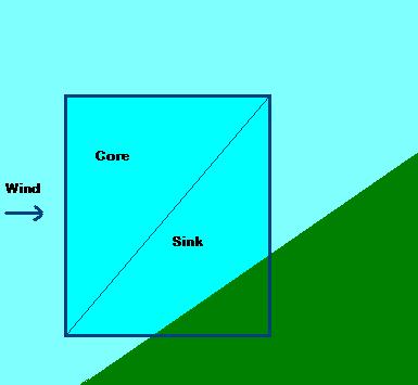 |
| Property | Description |
| Generic Action Properties | See description above. Note that RealismOverrides objects do not have an InstanceID. |
| Activated |
Set to True or False. This can be changed during a mission using the Object Activation action. |
| ObjectReference |
A reference to an AreaDefinition object that defines a box that is the bounding area of the ridge lift. It is very important that the heading setting of the AreaDefinition points in the same direction as the slope (to the left in the above diagram). |
| AirObjectModelGuid | An optional model GUID. The model will be rendered within the ridge lift box. |
| ScaleModel | Set to True to if the model should be scaled to match the size of the ridge lift box. Set to False to render the model to its own scale. |
| CoreRateScalar | A scalar value that is applied to the wind in the Core area of the ridge lift. A positive value will provide an updraft, a negative value a downdraft. Typically a positive value such as 0.5 would be entered here. So if the wind speed was 8 m/s, an updraft of 4 m/s would be applied. |
| CoreTurbulence | A variation scalar that is applied to the wind speed. For example, if a value of 0.1 is entered, and the wind speed is 8 m/s, the wind speed in the ridge lift Core area will be randomly varying between 7.2 and 8.8 m/s. |
| SinkRateScalar | A scalar value that is applied to the wind in the Sink area of the ridge lift. A positive value will provide an updraft, a negative value a downdraft. Typically a negative value such as 0.5 would be entered here. So if the wind speed was 8 m/s, an downdraft of 4 m/s would be applied. |
| SinkTurbulence | A variation scalar that is applied to the wind speed. For example, if a value of 0.1 is entered, and the wind speed is 8 m/s, the wind speed in the ridge lift Sink area will be randomly varying between 7.2 and 8.8 m/s. |
Scenario Metadata
The scenario metadata provides information that the mission system uses to place the mission appropriately in the list of missions presented to the user. See the explanation in the tutorial for an example.
| Property | Description |
| Generic Action Properties | See description above. |
| ScenarioType |
Text to describe the scenario. This is for your own use and does not appear on the screen. |
| IsMultiplayer | True or False. Default is False. |
| SkillLevel |
One of:: Beginner, Intermediate, Advanced, or Expert. |
| LocationDescr | Enter a text string that describes the location. |
| DifficultyLevel | An integer determining the order in which the mission will appear after sorting. The lower the number the earlier it will appear in the list. Refer to the difficulty level numbers provided with other missions to determine the appropriate number here. |
| EstimatedTime |
Enter a text string that estimates how long the mission will take. |
| UncompletedImage | Filename for a bitmap containing the image to appear on the screen in the image list, when the mission has not been completed. Should be 380 pixels wide x 232 pixels in height, either 256 color or 5-6-5 format. Use the Imagetool utility to convert 24 bit bmp files to 5-6-5 format. |
| CompletedImage | Filename for a bitmap containing the image to appear on the screen in the image list, after the mission has been completed at least once. Should be 380 pixels wide x 232 pixels in height, either 256 color or 5-6-5 format. |
| ExitMissionImage | Filename for a bitmap containing the image to appear in the End Mission dialog. Should be 86 pixels wide x 86 pixels in height, either 256 color or 5-6-5 format. |
| MissionBrief | Filename of an HTML file containing the mission briefing. The file can contain images (such as maps) and text describing the stages and goals of the mission. |
| AbbreviatedMissionBrief | Short version of the mission brief, used when the mission is being repeatedly played by the user. |
| SuccessMessage | The message that will be displayed once the mission ends and the user has completed the mission objectives. In this case the UncompletedImage will be replaced by the Completed image in the Missions list. |
| FailureMessage | The message that will be displayed once the mission ends and the user has failed the mission. |
| UserCrashMessage | The message that will be displayed once the mission ends and if the user has crashed. |
| CategoryRef | To set the category GUID in your metadata cut and paste the value out of this Category file. Categories include Tutorials, Backcountry, Military, Airline Pilot, etc. |
Thermal
A thermal object can be used to simulate atmospheric effects, including thermals and downdrafts. Refer also to the Weather Systems documentation.
 |
| Property | Description |
| Generic Action Properties | See description above. Note that RealismOverrides objects do not have an InstanceID. |
| Activated |
Set to True or False. This can be changed during a mission using the Object Activation action. |
| ObjectReference |
A reference to an AreaDefinition object that defines a box that is the bounding area of the thermal. Note that this box defines the position of the thermal, including its starting height above the ground, and the height of the thermal. |
| AirObjectModelGuid | An optional model GUID. The model will be rendered within the thermal box. |
| ScaleModel | Set to True to if the model should be scaled to match the size of the thermal box. Set to False to render the model to its own scale. |
| SinkTransitionSize | The width in meters of the transition layer between the Sink and the atmosphere outside of the thermal. Half of the width of this transition will be outside the radius of the Sink layer, and half within. |
| SinkLayerSize | The width in meters of the Sink layer. |
| CoreTransitionSize | The width in meters of the transition layer between the Core and the Sink of the thermal. Half of the width of this transition will be outside the Core, and half within. |
| CoreSize | The radius in meters of the Core of the thermal. |
| BaseHeight | The size of the transition layer, in meters, at the base of the thermal. The default is 50m. This is not the height of the thermal above the ground. |
| TopHeight | The size of the transition layer, in meters, at the top of the thermal. The default is 50m. This is not the height of the thermal. |
| SinkRate | The lift value, in meters per second, within the Sink layer. A positive value will provide an updraft, a negative value a downdraft. |
| SinkTurbulence | A variation in meters per second that is applied to the SinkRate. For example, if a value of 1.5 is entered, and the SinkRate is -3 m/s, the actual sink rate applied will be randomly varying between -1.5 m/s and -4.5 m/s. |
| CoreRate | The lift value, in meters per second, within the Core layer. A positive value will provide an updraft, a negative value a downdraft. |
| CoreTurbulence | A variation in meters per second that is applied to the CoreRate. For example, if a value of 1.5 is entered, and the CoreRate is 5 m/s, the actual core rate applied will be randomly varying between 3.5 m/s and 6.5 m/s. |
Volume Race Point
A volume race point specifies one or more areas that are to be entered as part of a race.
| Property | Description |
| Generic Action Properties | See description above. |
| OnEnterActions | The actions initiated when the race point is successfully negotiated. |
| OnEnterCondition | If the ConditionPenalty is set to zero, the conditions specified here must be met before the OnEnterActions will be initiated. If the ConditionPenalty is greater than zero, the OnEnterActions will be initiated whether the specified conditions are met or not, but if they are not met the ConditionPenalty will be added to the players race time. |
| Areas | A list of AreaDefinition objects, defining the volume. |
| ConditionPenalty | If this is greater than zero, it is the time penalty for failing to meet the OnEnterCondition. |
| Maneuver | Maneuver icon to display, refer to the List of Maneuvers. The default is None. |
Scenery Objects
Scenery objects can be added to the world, to appear only when the mission is being undertaken. Scenery objects take the following properties:
| Property | Description |
| Descr | The name of the scenery object. The system will generate a name based on the type of object, simply be appending the number of the next scenery object to the name of the scenery. This name can be edited to help identify it further. Make sure though that the name is unique. |
| WorldPosition | Latitude, longitude, and altitude in feet. For example: N22°21' 44.68",E114° 1' 15.01",+000000.00 |
| Orientation | Pitch, Bank and Heading, or orientations about the three axis, in degrees. |
| MDLGuid | GUID of the object model, from the list of Library Objects. |
| AltitudeIsAGL | Set to True if the altitude in WorldPosition is above ground level, set to False if the altitude is above mean sea level. |
| Scale | A scaling factor can be applied to the model. The default is 1.000 (no scaling). |
| ImageComplexity | The minimum scenery complexity setting the user must have set in order for this object to be rendered. One of: VerySparse, Sparse, Normal, Dense, VeryDense, ExtremelyDense. |
| Effect | Reserved for internal use, when saving off a mission/flight file. |
| ModelAnimation | Reserved for internal use, when saving off a mission/flight file. |
| Activated | Set to True or False. This can be changed during a mission using the Object Activation action. |
Mobile Scenery Objects
Mobile scenery objects can be added to the world, to appear only when the mission is being undertaken. Mobile scenery objects take the following properties:
| Property | Description |
| InstanceID |
This is the GUID generated to ensure the object has a unique reference. Do not edit this field |
| Activated | Set to True or False. This can be changed during a mission using the Object Activation action. |
| ModelID | GUID of the object model. |
| WorldPosition | Latitude, longitude, and altitude in feet. For example: N22°21' 44.68",E114° 1' 15.01",+000000.00 |
| Orientation | Pitch, Bank and Heading, or orientations about the three axis, in degrees. |
| IsOnGround | True or False. |
| SpeedKnots | The speed of the scenery object, in knots. |
| MSOWaypointController | An MSOWaypointController object. |
MSOWaypointController Object
The MSO (Moving Scenery Object) waypoint controller has the following properties.
| Property | Description |
| AccelKnots |
The acceleration that will always be used to increase or decrease the speed of the scenery object, in knots per second. |
| GroundCruiseSpeed | Ground speed in knots. |
| GroundTurnSpeed | Turning speed in knots. |
| GroundTurnTime | Time in seconds to make a 90 degree turn. A recommended minimum turn time is 0.5 seconds. |
| WaypointList | A Waypoint object list. |
Spawn List
A spawn list is a list of objects (AI aircraft, scenery objects, triggers, and actions) that should only appear in the mission when a certain stage in the mission has been reached. Spawn lists are initiated by Spawn actions. If the spawn action is called more than once, then multiple objects are created.
| Property | Description |
| id | Reserved. Do not edit this field. |
| Descr | The name of the spawn list. The system will generate a name such as SpawnList1. This name can be edited to help identify it further. Make sure though that the name is unique. |
| InstanceId | This is the GUID generated to ensure the object has a unique reference. Do not edit this field |
| Objects | The list of objects to be created. Click on Property Set for the Objects to bring up the list of objects in the Property Sets box. |
Triggers
Triggers initiate actions. There are eleven different types of triggers. When they are active, they will fire whenever the appropriate conditions are met. When a trigger is deactivated it is not evaluating its conditions to decide whether it should fire its actions.
In multiplayer mode, triggers with the IsGlobal property set to True will affect all other players. If a trigger does not contain this property, or the property is set to False, the trigger will affect only the local player.
- Generic Trigger Properties
- Airport Landing Trigger
- Area Landing Trigger
- Collision Trigger
- Counter Trigger
- Last Lap Trigger
- Menu Prompt Trigger
- Parking Trigger
- Property Trigger
- Proximity Trigger
- Race End Trigger
- Timer Trigger
Generic Trigger Properties
All triggers include the following properties (except where noted in the descriptions below).
| Property | Description |
| id | Reserved. Do not edit this field. |
| Descr | The name of the trigger. The system will generate a name such as AirportLandingTrigger1, simply be appending the number of the next trigger to the type of trigger. This name can be edited to help identify it further, though it is a good idea to maintain the type of trigger in the name, as this information is not clearly available through any other mechanism. Make sure though that the name is unique. |
| InstanceId | This is the GUID generated to ensure the object has a unique reference. Do not edit this field |
| Activated | Set to True or False. This value can be changed during the mission with the Object activation action. |
| Latched | This will be False at the start of a mission and set to True when the trigger fires. Do not edit this property. |
| OneShot | Set to True if the trigger should only fire once during the mission. Note a few triggers do not contain this property, these are noted in the descriptions for those triggers. |
| Actions | List of one or more actions to initiate when the trigger is fired. Note a few triggers do not contain this property, these are noted in the descriptions for those triggers. |
Airport Landing Trigger
An airport landing trigger is fired when the user's aircraft (not AI controlled aircraft) lands on a runway.
| Property | Description |
| Generic Trigger Properties |
See description above. |
| AirportIdent | The airport identification code, such as KSEA for SeaTac International. |
| RunwayFilter | A RunwayFilter object. Click on the AirportLandingTrigger entry in the Property Sets box to show the RunwayFilter entry, and click on the RunwayFilter to bring up its properties. |
| LandingType |
One of: FullStop, TouchDown or Any. The default is FullStop. |
RunwayFilter Object
A runway filter object can be used to specify exactly which runway an aircraft is to land on.
| Property | Description |
| RunwayNumber |
Runway number, leave as 0 if any runway is acceptable. Runway numbers can be from 0 to 36, or one of: North, NorthEast, East, SouthEast, South, SouthWest, West or NorthWest. The default is 0 (none). |
| RunwayDesignator |
One of: None, Left, Right, Center, Water, A, or B. The default is None. |
Area Landing Trigger
An area landing trigger is fired when the user's aircraft (not AI controlled aircraft) lands on one in a specified list of areas.
| Property | Description |
| Generic Trigger Properties |
See description above. |
| Areas | List of areas which are to fire the trigger. These areas are defined as Area Definition Objects. If no areas are defined, the user can land anywhere and the trigger will fire. |
| LandingType |
One of: FullStop, TouchDown or Any. |
Collision Trigger
A collision trigger is fired when an object, typically the user aircraft, hits an object such as a gate or pylon. When an object has an associated collision trigger the default crash behavior is overridden, and the actions initiated by this trigger specify the collision effects. For example, if gates and pylons have collision triggers they might initiate a PlayAnimationAction to render the deflating pylon collapsing. Other appropriate actions might be the DisqualifyPlayerAction or the TimePenaltyAction.
| Property | Description |
| Generic Trigger Properties |
See description above. |
| ObjectFilter | One of: Anything, User or Reference, determining which objects can fire the trigger. Reference is unused. |
| ObjectReference | The library object that the collision trigger is attached to, typically a race pylon or gate. |
Counter Trigger
A counter trigger will fire when it is counter reaches a specified limit. The counter is incremented by Count Actions.
| Property | Description |
| Generic Trigger Properties |
See description above. |
| StartCount |
Integer indicating the count to start at. |
| StopCount |
Integer indicating when the count stops and the trigger fires. |
| Counter |
The current value of the counter. |
Last Lap Trigger
A last lap trigger fires when the local user starts the last lap of the race.
| Property | Description |
| Generic Trigger Properties |
See description above. |
Menu Prompt Trigger
A menu prompt trigger will create a menu of options for the user. For some missions this can be as simple as the option to continue, and the option to turn back.
| Property | Description |
| Generic Trigger Properties |
See description above. There is no Actions property for a Menu Prompt trigger. |
| Text |
The text to precede the list of menu options. The maximum length of this text is equivalent to 37 "M"s. |
| MenuItem |
A list of menu items.Clicking on the MenuItem Property Set will bring up the Objects dialog. Click New to add as many menu items as you need. The menu items will appear in the Property Sets box of the Objects tab of the main Object Placement Tool dialog, and clicking on them will bring up their properties. |
MenuItem Object
Menu item objects form the options for a Menu Prompt trigger.
| Property | Description |
| Descr |
The name of the menu item. The system will generate a name such as MenuItem1. This name can be edited to help identify it further. Make sure though that the name is unique. |
| Text |
The text for the menu item. The maximum length of this text is equivalent to 40 "M"s. |
| Actions |
The list of actions to perform if the menu item is selected by the user. |
Parking Trigger
A parking trigger will fire when the user has reached the parking spot assigned by the ATC at the airport specified. When allocating a parking space to an aircraft, a radius based on half the wingspan defined in the [aircarft_geometry] section of the Aircraft Configuration File is used.
| Property | Description |
| Generic Trigger Properties |
See description above. |
| AirportIdent |
The airport identification code, such as KSEA for SeaTac International. |
Property Trigger
A property trigger fires when one or more conditions are met. These conditions can be based on aircraft speed, altitude, failure of components, or a whole host of other simulation variables. See the explanation in the tutorial for an example.
| Property | Description |
| Generic Trigger Properties |
See description above. Property triggers are only ever fired once, and do not have a OneShot property value. |
| Condition |
One or more conditions, created using the Conditional Editor, which can be a list of logical AND, or a list of logical OR, conditions. Click on the Property Set for Condition to bring up the Conditional Editor dialog. |
Note
There is an issue with many of the floating point properties (such as Ground Speed), in that they cannot reliably be tested to being equal to zero in a condition. Mission designers should check for floating point values being less than a certain small value, rather than check for equality with zero. For example, check Ground Speed is less than 1kt to detect a "stopped" aircraft.
Proximity Trigger
A proximity trigger is fired when the specified object, usually the users aircraft, enters a given box. See the explanation in the tutorial for an example.
| Property | Description |
| Generic Trigger Properties |
See description above. The proximity trigger does not include the Actions property, as greater flexibility is provided by additional properties. |
| IsGlobal | Set to True to specify the actions of the trigger firing apply to all players, False to specifiy they only apply to the triggering player. |
| ObjectFilter |
This can be one of: User, Reference or Anything. The default is User, which means only the user aircraft can fire the trigger. If it is set to Reference, then only the objects listed for OnEnterFilter and OnExitFilter can fire the trigger. If it is set to Anything then any aircraft can fire the trigger. If it is set to User or Anything then OnEnterFilter and OnExitFilter are ignored. |
| OnEnterActions |
List of actions to be triggered when a specified object enters the box, and the OnEnterCondition is met. |
| OnEnterCondition | Conditions that must be met for the OnEnterActions to be initiated. |
| OnEnterFilter | List of objects that will fire the OnEnterActions on entering the box, if the OnEnterCondition is met. |
| OnExitActions |
List of actions to be triggered when a specified object leaves the box, if the OnExitConditions are met. |
| OnExitCondition | List of conditions that must be met for the OnExitActions to be initiated. |
| OnExitFilter | List of objects that will fire the OnExitActions on leaving the box, if the OnExitConditions are met. |
| Areas | List of one or more 3D box areas that the trigger applies to. These are set up as AreaDefinition objects. |
Note
If a proximity trigger has its OneShot property set to True, and it has on-enter and on-exit actions (or on-enter and on-exit conditions) the trigger will deactivate itself on the first set of actions. So in other words, when the on-enter actions fire, the proximity trigger will be deactivated and the on-exit actions will never fire.
So if you are going to use both on-enter and on-exit actions or conditions, or any combination, you must set the trigger so that OneShot is set to False.
Race End Trigger
A race end trigger is fired either when the user crosses the finish line, or when the user has finished in a specified place.
| Property | Description |
| Generic Trigger Properties |
See description above. |
| Place | If this is set to 0, the trigger will fire when the local user crosses the finish line, typically the last gate of the last lap, in a race. This will not necessarily be when the race is over. If this is set to a non-zero integer, the trigger will fire only when the race is completely finished and the local user has finished in the place specified. This second option allows for the granting of rewards when the user finishes, for example, in 1st, 2nd, or 3rd place. |
Timer Trigger
A timer trigger fires when the given number of seconds has elapsed. See the explanation in the tutorial for an example.
| Property | Description |
| Generic Trigger Properties |
See description above. |
| CurrentTime |
Current amount of time, in seconds, left before the trigger fires. Do not set this property. |
| StartTime |
The time, in seconds, when the timer is to start. |
| StopTime |
The time, in seconds, when the timer is to stop, and fire any actions linked to the trigger. |
| OnScreenTimer |
Set to True if an onscreen timer is to be rendered. Note that there can only be one onscreen timer (so if a new one is opened, it will replace any existing one). The default is False. |
| StaysVisible | Set to True if the timer is to stay visible after the StopTime has been reached, typically so that a player can view their mission time. The default is True. |
| IsGlobal | Set to True to specify the actions of the trigger firing apply to all players, False to specifiy they only apply to the triggering player. |
Goal Object
There is only one type of goal, and a mission can include one or more goals. See the explanation in the tutorial for an example.
| Property | Description |
| id | Reserved. Do not edit this field. |
| Descr | The name of the goal. The system will generate a name such as Goal1. This name can be edited to help identify it further. Make sure though that the name is unique. |
| InstanceId | This is the GUID generated to ensure the object has a unique reference. Do not edit this field |
| Activated | Set to True or False.This can be changed during a mission using the Goal Resolution action. |
| GoalState | One of: pending, completed, or failed. |
| Text | The text that will appear in the End Mission dialog, along with the final GoalState. |
| Order | The order in which the goals are to appear in the End Mission dialog, starting with 0 for the first. |
Disabled Traffic Airports Object
A disabled airport will not be involved in any AI traffic, either as a starting point or a destination.
| Property | Description |
| AirportIdent |
The airport identification code, such as KSEA for SeaTac International. |
Sample Missions
To examine the XML of the missions provided with ESP, click on the links below. The sample missions are from Microsoft Flight Simulator™.
Tutorials
| Tutorial 01 | Basic training, familiarizing users with the simulator and with rudimentary flight concepts. |
| Tutorial 02 | Basic training with visual cues for flight navigation. |
| Tutorial 03 | Basic training with viusual cues for flight navigation and crash detection. |
| Tutorial 06 | Landing training using a GPS system. |
| Tutorial 09 | Basic helicopter training. |
| Tutorial 10 | Helicopter takeoff and landing. |
| Tutorial 11 | Helicopter maneuvering with visual cues, and landing on a moving platform. |
| Tutorial 12 | Advanced helicopter maneuvering with visual cues, and landing on a moving platform. |
| Carrier Tutorial | Carrier takeoff and landing. |
Airline Pilot
| Monsoon | An IFR approach in a heavy, during extreme weather and including windshear effects. |
| Quito | A high altitude short approach into Quito Ecuador. |
Backcountry
| Congo | Twin engined cargo plane suffers a single engine failure on a paramilitary relief mission. |
Challenges
| Limited Options | Decision making after both engines fail due to a fuel leak on a commercial flight. |
Emergency
| Foul Weather | Bad weather search for a capsized boat, and rescue of an injured person from the sea. |
The Good Life
| Channel Crossing | Beginner IFR mission, using the ATC system. |
| Hawaiian | Sightseeing excursion, with whale spotting as a highlight. |
| Swiss Outing | Demonstrates a catestrophic engine oil pump failure. |
Military
| Rocket Launch Air Cover | Realistic homeland defense interception. |
| Carrier Practice | An evening carrier landing, with tight tolerances and possible refueling in challenging weather. |
Pilot for Hire
| 747 Test | Illustrates complex system failures. |
| Oil Rig | Search and rescue, with complex scenery and explosive effects. |
Test Pilot
| Vomit Comet | Aerobatic test of skills, including performing zero-G parabolas. |
Racing (Single Player)
| Reno Air Racing Practice | Racing against recorded AI controlled aircraft, and includes some system failures. |
Racing (Multi-Player)
| Reno Flying Start Easy | Basic multiplayer racing. |
| Reno Pace Start | Complex multiplayer race, including interaction with AI controlled objects. |
Manual Editing of Mission Files
The Object Placement Tool, used to create mission XML files, cannot quite handle all the variations to the XML logic that the mission system within ESP can process correctly. This section details where manual editing is required.
- Complex Condition Statements
- Testing that an Object Exists
- Starting AIPlayback
- Incorrect Type Entry
Complex Condition Statements
Complex conditions involving combinations of AND and OR logic cannot be entered using the Condition Editor of the Object Placement Tool.
The example shown is equivalent to the following logic:
IF (bank degrees > 150 AND bank degrees < 179.5)
OR
(bank degrees < -179.5 AND bank degrees > -150 degrees)
THEN ... OnEnterCondition has been met.
Testing that an Object Exists
The SimMission.Exists property is not available in the Object Placement Tool. Use this test to see whether an object has been destroyed (or not) in missions involving the sling or hoist system. Clearly the outcome of a mission may well depend on whether the transported object is still intact at the drop off point!
Starting AIPlayback
AIPlayback can be initiated with a timer or other Trigger, but because of possible short delays in starting the playback, the AirplanePlaybackAI entry can be used to start the playback quickly. There is also an incompatibility between this manual entry and the Object Placement Tool. If the tool is used after this entry is made, the <TimeStamp> entry is deleted, and will need to be entered again.
Incorrect Type Entry
The Simvar.CylindersFailed property is incorrectly entered as a Double in the Object Placement Tool. This should be manually changed to a Ulong. This also applies to the CABLE CAUGHT BY TAILHOOK variable.
.jpg)