MT3620 hardware notes
The topics covered in this section reflect updated guidance from MediaTek in their MT3620 hardware design documents and data sheet. For further details about these topics please refer to the MediaTek MT3620 documentation.
RTC power requirements
If the MT3620 is configured to use the on-board real-time clock (RTC) with a 32KHz crystal, you must ensure that the RTC will be powered at start-up or the system will hang. You can do this by simply connecting system power to the RTC power input (MT3620 pin 71). However, if your application requires a backup power source for the RTC, MediaTek recommends that you incorporate, in your design, a way to automatically switch between backup power and system power.
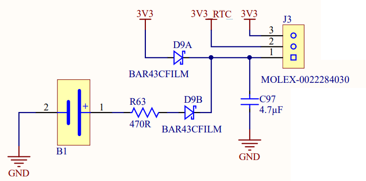
The following circuit appears in the MediaTek MT3620 Hardware Design Guide, and illustrates both ways of powering the RTC on the MT3620. The setting of J3 determines whether system power directly powers the RTC or whether a battery backup circuit powers the RTC. When a jumper connects pins 2 and 3 of J3, the 3V3_RTC (RTC power input) power rail is directly connected to system power. When the jumper connects pins 1 and 2 of J3, then 3V3_RTC is powered by either the system power or the battery backup circuit, depending on which has the highest supply voltage. Hence, the backup battery is typically used only when the system power is unavailable.
ADC/GPIO voltage level requirements
The MT3620 ADC input pins can also be configured as GPIO pins. This is a potential source of confusion because when used as GPIO pins they can operate at 3.3 volts, whereas when used as ADC inputs the maximum input voltage cannot exceed 2.5V. Additionally, the voltage reference for the MT3620 (VREF_ADC) has a maximum voltage of 2.5V so analog signals greater than 2.5V will exceed the full-scale range of the ADC. To handle analog signals at higher voltages, designers should use external filters or external ADC devices.
Power Down considerations
The MT3620 is suitable for use in battery-powered applications. Battery-powered devices typically need to operate on a strict power budget. Applications can be designed to take advantage of MT3620 features such as Power Down to minimize power consumption. The Power Down feature enables an app to transition the MT3620 to the Power Down state, which is the lowest possible power state other than being fully powered off. In the Power Down state for the MT3620, the typical current consumption is ~0.01mA if the 3V3 supply to MT3620 can be fully controlled by the EXT_PMU_EN signal, or ~0.02mA otherwise. Note that these figures relate to MT3620's power consumption, not to any other hardware supplied by the same 3V3 supply.
The Azure Sphere Hardware Designs repository on GitHub includes a hardware reference design (folder P-MT3620EXMSTLP-1-0) that demonstrates how to integrate MT3620 into a low-power design where the MT3620 achieves its lowest-power state but wakes to provide cloud-based operations. The design incorporates an external very-low-power microcontroller that can respond to external input such as button presses.
For more MT3620-specific hardware information about the real time clock and Power Down, see MT3620 Real Time Clock / Power Down Application Note from MediaTek.
Note
MediaTek uses the name "RTC mode" to define the state where everything is turned off except the RTC (Real Time Clock). Microsoft Azure Sphere refers to this state as "Power Down."
Interacting with an MT3620 in Power Down state
When the MT3620 is in the Power Down state, it will be unresponsive to CLI commands or attempts to deploy a new or updated image from Visual Studio and Visual Studio Code.
If you are using a board implementing the latest version of the MT3620 Programming and Debugging interface, the reset button will wake the board from Power Down state and the PC is able to wake the board when you issue an az sphere device restart or az sphere device recover command. However, if you are using a board with an older version of this interface, the reset button on the development board will not work and these commands will not wake the board.
We recommend that, during development, your application allow at least 30 seconds of uptime after startup before going into Power Down state to enable the PC to control the MT3620 before it goes into Power Down. One way of achieving this is to use a timer to avoid entering Power Down before 30 seconds have elapsed after your application starts. Another way is to configure your application not to enter Power Down if a specific button is held down.
If your application allows sufficient uptime after startup, perform the following steps to restart the device and delete the application image from the device:
Note: The device must have the
appDevelopmentcapability to do the following.- While in Power Down state, restart the device by doing one of the following:
- Use the command
az sphere device restartor press the reset button. (Note: this option does not work when using older versions of the programming/debug interface. In this case, use one of the options below instead.) - Disconnect the board from its power source and then, after a short interval, reconnect it.
- Briefly connect the WAKEUP pin to any ground pin.
- Use the command
- Wait a few seconds for the Azure Sphere OS to boot so that it is responsive to CLI commands.
- Run the command
az sphere device sideload deleteto remove the application image from the device.
- While in Power Down state, restart the device by doing one of the following:
If the your application does not allow sufficient uptime after startup you can still recover the device by doing the following:
- Hold down the physical Reset button while performing the following steps:
Disconnect the board from its power source and then reconnect it. (Note: if you are using the latest version of the programming/debug interface, this step is not necessary.)
Wait 5-10 seconds so that the USB connection to the PC is ready.
If you are using Linux, run the
sudo /opt/azurespheresdk/DeviceConnection/azsphere_connect.shcommand to re-enable communication with the device.Run the command
az sphere device recover.Wait until the following message is displayed at the command line:
Board found. Sending recovery bootloader.
- Release the reset button to start recovery.
- Hold down the physical Reset button while performing the following steps:
Pinout settings
The following pins can be used with the Power Down feature:
Pin 81 | PMU_EN
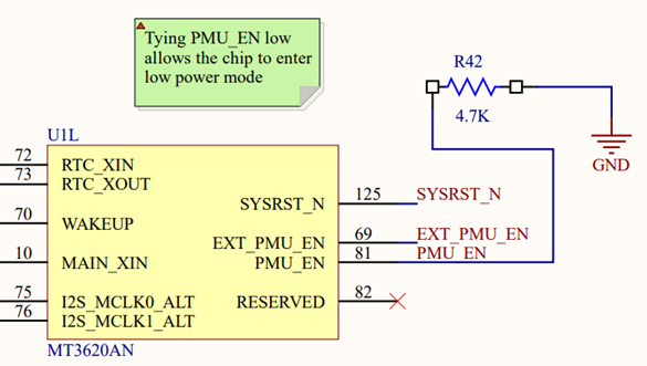
This pin must be tied low to allow the chip to enter Power Down state.
The voltage on the PMU_EN pin controls whether the MT3620 can enter Power Down state. It is recommended that you pull this pin low, unless low-power functionality is not desired. For example, in the following circuit the PMU_EN pin is pulled low (set to logic zero) via pull-down resistor R42.
Pin 70 | WAKEUP
This is the input GPIO pin that can be used to trigger a wakeup for event-driven scenarios when driven low.
WAKEUP is an input that can be used to bring the chip out of Power Down state. The WAKEUP signal is active low; it should be pulled high during normal use and pulled low to wake the chip.
Pin 69 | EXT_PMU_EN
This pin is an output that turns off the main power supply to the chip when the chip enters Power Down state.
The EXT_PMU_EN signal is intended to be connected to the enable pin of the external voltage regulator powering the chip. When the chip enters Power Down state, EXT_PMU_EN transitions from high to low, thus disabling the external voltage regulator. Adopting this design approach will reduce the Power Down current consumption to approximately 0.01mA, whereas leaving the external voltage regulator enabled during Power Down results in a current consumption of around 0.02mA.
Measuring power consumption in low-power designs
When designing devices that utilize the Power Down feature, it is often useful to add a means of measuring supply current to the MT3620. For example, if you are designing a device based on an MT3620 module, include in your prototype design a sense resistor in series with the main 3.3V power supply to the module. The voltage developed across the sense resistor can then be measured and the supply current calculated.
Power Profile considerations
Azure Sphere power profiles enable a high-level application to adjust the balance between performance and energy savings at run time. The Azure Sphere OS dynamically adjusts the CPU frequency to balance power consumption and performance according to the specified Power Profile.
The default power profile for the MT3620 is HighPerformance.
The MT3620 only supports frequency scaling. It does not support dynamic voltage scaling.
The supported frequencies are:
- 165 MHz
- 198 MHz
- 247 MHz
- 329 MHz
- 494 MHz
Although the system will remain fully functional at lower frequencies, there might be slight impact on performance. For example, at lower CPU frequency, peripherals will still operate at supported bus frequencies (such as UART baud rates) but overall throughput might be slightly slower for applications.
Disable Wi-Fi RF front end on MT3620
The MT3620 has an on-chip, Wi-Fi module. In designs where Wi-Fi is not required, the RF front-end components can be excluded from the hardware design.
Analog front-end RF pins on the MT3620
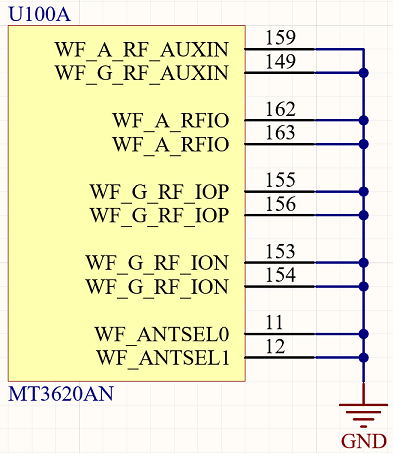
Where Wi-Fi is not required, MediaTek recommends tying any unused Wi-Fi RF pins (WF_XXXXXX) to ground (as shown below). This eliminates noise on the RF analog path.
Wi-Fi Processor power pins on the MT3620
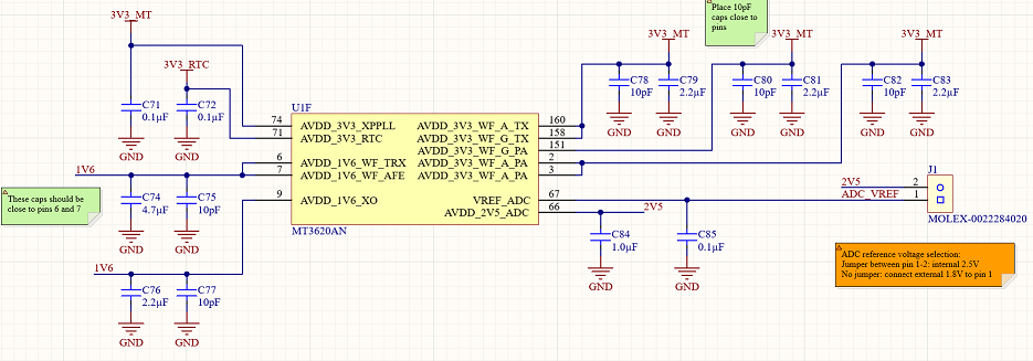
The Wi-Fi processor cannot be powered down, but will go into a sleep mode when the transmitter is disabled. Therefore, power needs to be applied to the MT3620 pins that provide power to the Wi-Fi subsystem. For example, refer to the MT3620 Wi-Fi subsystem power connections, shown on the right, in the diagram below.
Note
When you disable Wi-Fi using software control MT3620 power consumption will decrease. Power consumption will decrease further if you connect the Wi-Fi RF pins to ground. The exact reduction in power consumption will depend on your hardware design.
Software control of the Wi-Fi interface
Refer to Networking_SetInterfaceState function for further details.
Feedback
Coming soon: Throughout 2024 we will be phasing out GitHub Issues as the feedback mechanism for content and replacing it with a new feedback system. For more information see: https://aka.ms/ContentUserFeedback.
Submit and view feedback for