MCU programming and debugging interface
The MT3620 exposes two dedicated UARTs and two control signals (reset and recovery) for use during device provisioning and recovery. In addition, an SWD interface is available for debugging RTApps and a further UART is reserved for Microsoft diagnostics.
The Azure Sphere PC software tools require the use of a USB-to-UART interface chip that exposes these interfaces to a PC in a way that allows the tools to recognize and interact with them. The Azure Sphere tools include support for loading an application over USB by using the Service UART and for recovering the Azure Sphere OS by using the Recovery UART. The PC tools require the use of the Future Technology Devices International (FTDI) FT4232HQ UART-to-USB interface chip to expose the interfaces. Currently, the tools do not support other FTDI chips or interface chips from different manufacturers.
For development boards, this interface chip is usually on the same PCB as the MT3620. This approach is documented in the MT3620 reference development board (RDB) design. For a custom board or module that uses the MT3620, it may be appropriate to have the interface chip on a separate PCB, because this hardware is required only during manufacturing or servicing, enabling per-unit cost savings. This approach is documented in the stand-alone programming and debugging interface board design.
Overview of ports
The MT3620 exposes three UARTs and an SWD interface that are used for programming, Microsoft diagnostics, and provisioning the chip. The four interfaces have the following functions:
Debug UART—The Debug UART enables Microsoft to perform diagnostics. Note that this UART is not usable for application debugging or diagnostics.
Under the direction of Microsoft, this interface provides a means of capturing additional diagnostic information that can be useful when debugging certain problems. It is therefore recommended to include this interface for devices that are used for software or hardware development, but it can be considered optional for devices that have reached the manufacturing stage.
SWD interface—The SWD interface is used when debugging real-time capable applications (RTApps) that run on the M4F cores; this interface is shared between the two M4F cores.
If you require the ability to debug RTApps (for example during device development), your device should support this interface. Once your device reaches the manufacturing stage, this interface can be considered optional and can be omitted.
Service UART—The service UART provides the main programming and debugging interface between the MT3620 and the host computer.
This interface enables all Azure CLI operations that require an attached device, except for recovery (as described in the next paragraph). Because the Service UART is the main interface between the MT3620 and the host computer, this interface must be available for devices that support software development, as well as during manufacturing of retail devices. If this interface is available for a device in-field, it can also be used by service engineers—for example, to load new versions of the app software, if the device does not receive cloud updates because it is not connected to the internet.
Recovery UART—The recovery port provides a means of recovering a device to the latest version of the operating system.
This interface must be supported during manufacturing, because recovering a device to the latest version of the operating system is a common task during device manufacture. However, after a device has been sold to a customer (and they have connected it to the internet), cloud updates will ensure the device is kept up to date with the latest version of the operating system..
Overview of components
The following diagram provides an overview of the main components of the 4-port FTDI interface and their interconnections with the MT3620:
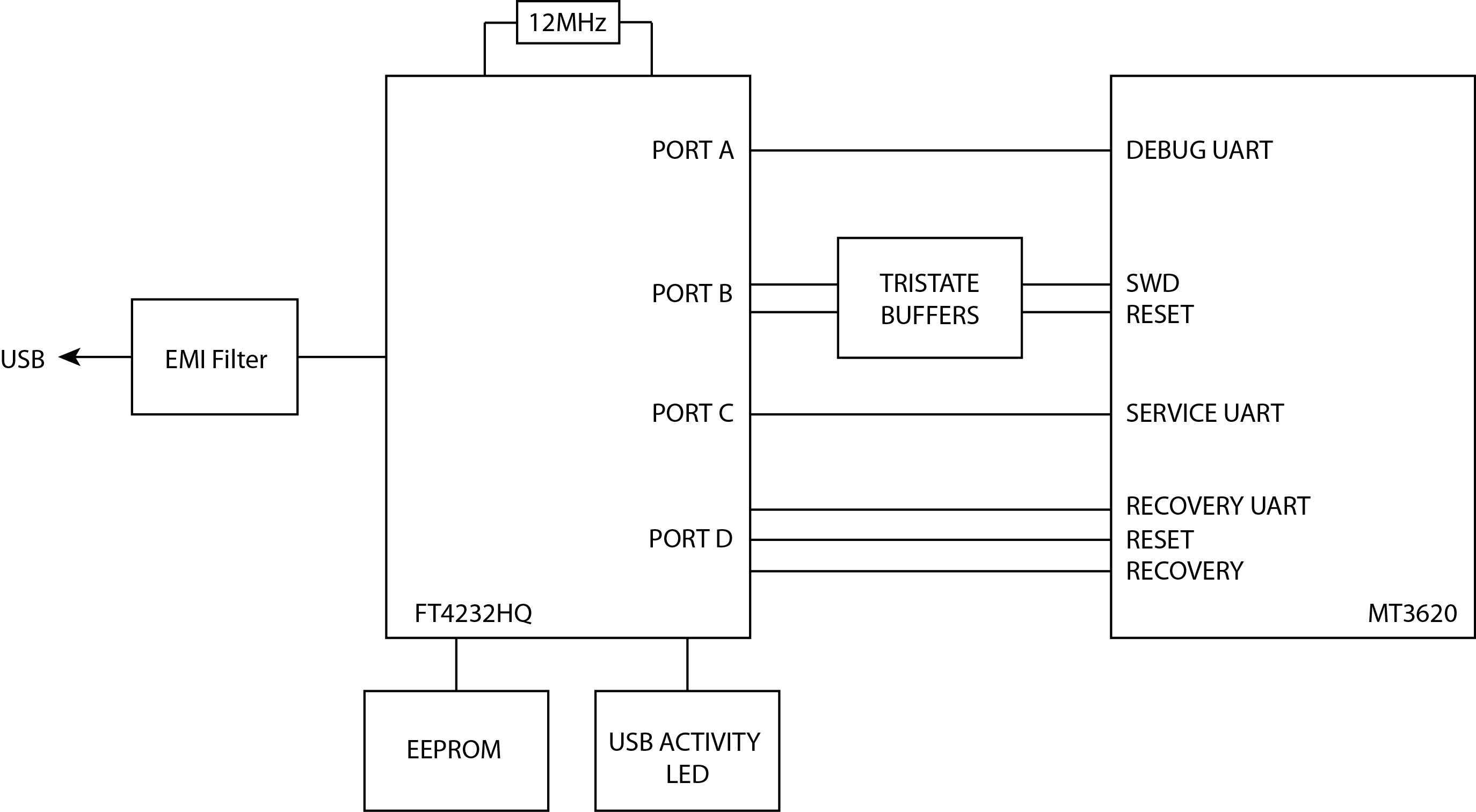
You may choose to use the FTDI chip and circuitry as a part of the same board as the MT3620 (for example, if you're building a development board) or in a separate interface board that sits between your MT3620 device and the PC.
Port assignments
To ensure compatibility with the PC tools, it is important to ensure that each of the exposed UARTs and the SWD interface that will be used in your design are connected to the FTDI ports as described in the following table.
| Function | FT4232HQ Pin Function (pin number) | MT3620 Pin Function (pin number) | ||
|---|---|---|---|---|
| Recovery UART, reset and recovery strapping pin | Port-D | DDBUS0 (48) | RECOVERY_RXD (134) | |
| DDBUS1 (52) | RECOVERY_TXD (135) | |||
| DDBUS2 (53) | RECOVERY_CTS (137) | |||
| DDBUS3 (54) | RECOVERY_RTS (136) | |||
| DDBUS5 (57) | DEBUG_RTS (96)* | |||
| DDBUS6 (58) | SYSRST_N (125) (and optionally WAKEUP (70) via circuit detailed below) | |||
| Service UART | Port-C | CDBUS0 (38) | SERVICE_RXD (129) | |
| CDBUS1 (39) | SERVICE_TXD (127) | |||
| CDBUS2 (40) | SERVICE_CTS (130) | |||
| CDBUS3 (41) | SERVICE_RTS (128) | |||
SWD and reset |
Port-B | BDBUS0 (26) | SWCLK | See SWD interface for details of SWD circuitry |
| BDBUS1 (27) | SWDIO out | |||
| BDBUS2 (28) | SWDIO in | |||
| BDBUS4 (30) | SWDIO direction | |||
| BDBUS5 (32) | SWD enable | |||
| BDBUS6 (33) | SYSRST_N (125) (and optionally WAKEUP (70) via circuit detailed below) | |||
Debug UART |
Port-A | ADBUS0 (16) | DEBUG_RXD (94) | |
| ADBUS1 (17) | DEBUG_TXD (95) | |||
| ADBUS2 (18) | DEBUG_CTS (97) | |||
| ADBUS3 (19) | DEBUG_RTS (96)* | |||
*DEBUG_RTS is one of the MT3620's 'strapping pins' which, if pulled high during a chip reset, causes the chip to enter recovery mode. At all other times, this pin is the RTS pin of the Debug UART.
Schematics
The following schematics show the main components required to support the FT4232HQ chip. The MT3620 reference board design provides a reference design incorporating this schematic.
Schematic 1:

Notes—Schematic 1:
- The 1K resistors in series with the reset line are included to avoid a short circuit in the event a user presses the reset button (if included in the design) at the same time that the reset line is being controlled programmatically during recovery.
- When laying out the PCB, ensure that the differential pair, USB_P and USB_N, are routed parallel to each other to give a characteristic differential impedance of 90Ω.
- The 33Ω resistors in series with the (optional) SWD lines are intended to reduce transients and should be placed close to the FT4232HQ.
Schematic 2:

Notes—Schematic 2:
- SYSRST_N is pulled high with a 100K resistor (R8). This means that the chip reset is not asserted by default.
The following two elements are optional. If present, they allow the physical RESET button and the FTDI interface to the PC to automatically wake up the MT3620 when RESET would have been toggled. This is recommended for any design which uses Power Down mode where the reset button or the PC interface must continue to operate while in Power Down mode.
- A pair of Schottky diodes is connected in series between SYSRST_N and WAKEUP and the common cathode connection of the diodes is connected to the reset button and the FTDI reset signals. This prevents SYSRST_N from toggling low when WAKEUP toggles low.
- WAKEUP is pulled high with a 100K resistor that is connected to the 3V3_RTC power supply. The 100K resistance ensures that WAKEUP is toggled low when SYSRST_N is toggled low; the connection to 3V3_RTC ensures that WAKEUP will continue to be pulled high if the MT3620 power supply turns off for Power Down mode.
FTDI EEPROM
The FTDI interface chip provides a set of pins that must be connected to a small EEPROM that is used to store manufacturer's details and a serial number. After board assembly, this information is programmed into the EEPROM over USB using a software tool provided by FTDI, as described later in FTDI FT_PROG Programming Tool.
The following EEPROM parts are compatible with the FTDI chip:
- 93LC46BT-I/OT
- 93LC56BT-I/OT
- 93LC66BT-I/OT
Note the use of the LC variant, which is compatible with a 3.3V supply. For internal development purposes, Microsoft has always used the 93LC56BT-I/OT part.
Connect the EEPROM to the FTDI chip as follows:
| EEPROM circuit | Connection to FTDI chip |
|---|---|
 |
 |
UART interfaces
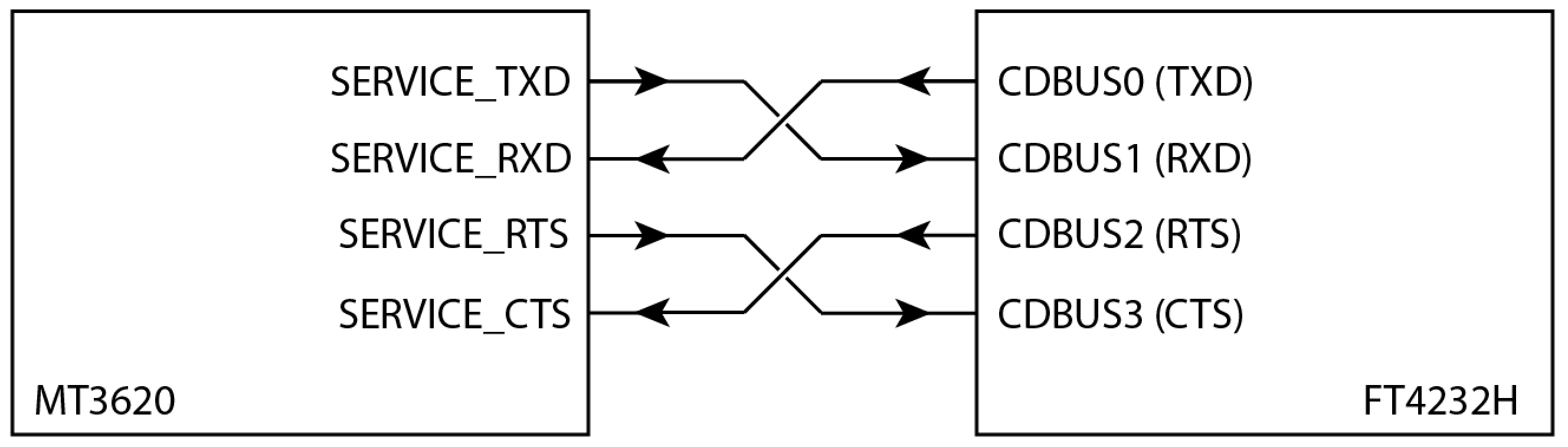
The Recovery, Service, and Debug UART connections between the MT3620 and the FTDI require no special circuitry. However, note the cross-over of TXD and RXD, and CTS and RTS. The FTDI documentation describes pin 0 of each port as TXD and pin 1 as RXD. These definitions are relative to the FTDI chip; that is, pin 0 is an output and pin 1 is an input. Consequently, it is necessary to cross over the RXD and TXD connections to the MT3620 (and similarly for CTS and RTS). The following diagram illustrates this for the Service UART; use the same scheme for the Recovery and Debug UARTs as well:
SWD interface
Although FTDI chips are typically used to provide a bridge between UARTs and USB, the Azure Sphere programming and debugging interface uses additional circuitry based on a quad tristate buffer to allow the FTDI part to operate as a high-speed SWD interface.
The following illustrates the required circuit and connection to the FTDI chip. Note that the SWDIO signal connects to the MT3620 pin 98 and SWCLK connects to pin 99.
| Tri-state buffer arrangement | FTDI Port-B connections |
|---|---|
 |
 |
USB activity LED (optional)
A USB activity LED can be useful to indicate data transfer over the USB connection during normal operation. You can implement a USB activity LED in several ways. The following circuit is merely an example.
The circuit ANDs together the clock and data lines that connect the FT4232HQ to the EEPROM. Although not obvious, these two lines toggle when data is being sent and received over USB and therefore can be used to indicate USB activity. However, the on-time of the output from the AND gate is too short to illuminate an LED; therefore, this signal is used to drive a mono-stable circuit, which in turn drives the LED.
The on-time of the mono-stable circuit is set to 100ms, so that even short bursts of USB traffic will cause the LED to illuminate.

FTDI FT_PROG programming tool
To help in programming the EEPROM, FTDI provides a free software tool called FT_PROG. The tool is available as both a Windows GUI application and as a command-line tool; both options are installed at the same time from the same package. Download the tool from the FTDI website and install it in the default location.
FT_PROG command-line tool
The command-line version of FT_PROG is the preferred method of programming the EEPROM, because it takes the name of a configuration file as a parameter and then programs multiple devices with a single command.
The Azure Sphere Hardware Designs repo on GitHub contains an EEPROM configuration file for use with the command-line tool. We strongly recommend that you use this file and the command-line tool in manufacturing scenarios. The configuration file programs the EEPROM with the following settings:
- Enables D2XX Direct mode and disables Virtual COM Port
- Auto-generates a serial number, beginning with 'AS'
- Sets Product Description to "MSFT MT3620 Std Interface"
To program the EEPROM, you must use this file as is without modification, because the Azure Sphere PC tools look for the Product Description string and will fail if this value is changed.
Step-by-step instructions for EEPROM programming
To use the command-line version of FT_PROG to program the EEPROM for a four-port FTDI chip:
Install the FTDI tools in the default location:
C:\Program Files(x86)\FTDI\FT_Prog.Connect one or more MT3620 boards to the PC.
Open a command prompt (for example, cmd.exe) and change to the folder where you saved the configuration file.
Type the following command to list all attached devices:
"c:\Program Files (x86)\FTDI\FT_Prog\FT_Prog-CmdLine.exe" scanIf four devices are attached, the output looks similar to this:
Device 0: FT4232H, MSFT MT3620 Std Interface, 984A8DD25A36
Device 1: FT4232H, MSFT MT3620 Std Interface, 984A8DD25A36
Device 2: FT4232H, MSFT MT3620 Std Interface, 984A8DD25A36
Device 3: FT4232H, MSFT MT3620 Std Interface, 984A8DD25A36
Type the following command to program all the attached devices. Specify the indexes of the attached devices (0, 1, 2, and so forth) after the
progandcyclparameters:"c:\Program Files (x86)\FTDI\FT_Prog\FT_Prog-CmdLine.exe" scan prog 0,1,2,3 MT3620_Standard_Interface.xml cycl 0,1,2,3The tool should display:
 Scanning for devices...
 Device 0: FT4232H, MSFT MT3620 Std Interface, 984A8DD25A36
 Device 1: FT4232H, MSFT MT3620 Std Interface, 984A8DD25A36
 Device 2: FT4232H, MSFT MT3620 Std Interface, 984A8DD25A36
 Device 3: FT4232H, MSFT MT3620 Std Interface, 984A8DD25A36
 Device 0 programmed successfully!
 Device 1 programmed successfully!
 Device 2 programmed successfully!
 Device 3 programmed successfully!
 Finished

 Re-enumerating Device 0....
 Re-enumerating Device 1....
 Re-enumerating Device 2....
 Re-enumerating Device 3....
To verify that programming was successful, scan once more:
"c:\Program Files (x86)\FTDI\FT_Prog\FT_Prog-CmdLine.exe" scanNote that the serial numbers have changes in the output and now start with AS:
Scanning for devices...
 Device 0: FT4232H, MSFT MT3620 Std Interface, AS5AW7FD
 Device 1: FT4232H, MSFT MT3620 Std Interface, AS5AHG3C
 Device 2: FT4232H, MSFT MT3620 Std Interface, AS5DWM2I
 Device 3: FT4232H, MSFT MT3620 Std Interface, AS5JQ0LJ
FT_PROG GUI application
The Windows GUI version of the application is useful for reading and checking the state of the EEPROM information. You can also use it to change the information; however, we recommend the use of the command-line version of the tool to program the device.
After you start the application, click the Scan button (with the magnifying glass icon) to read and display the current contents of the EEPROM.
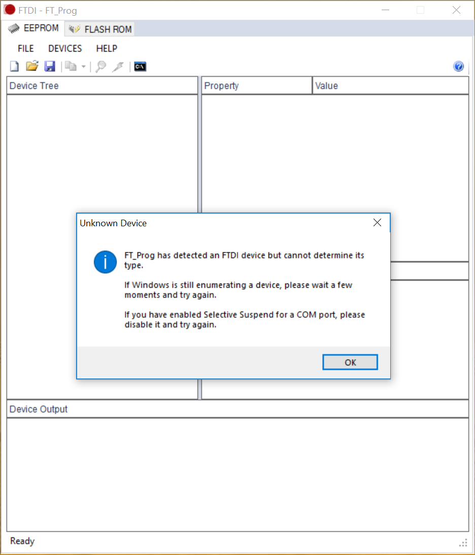
If an Unknown Device dialog box appears, as in the following example, click OK until the application window displays the information correctly.
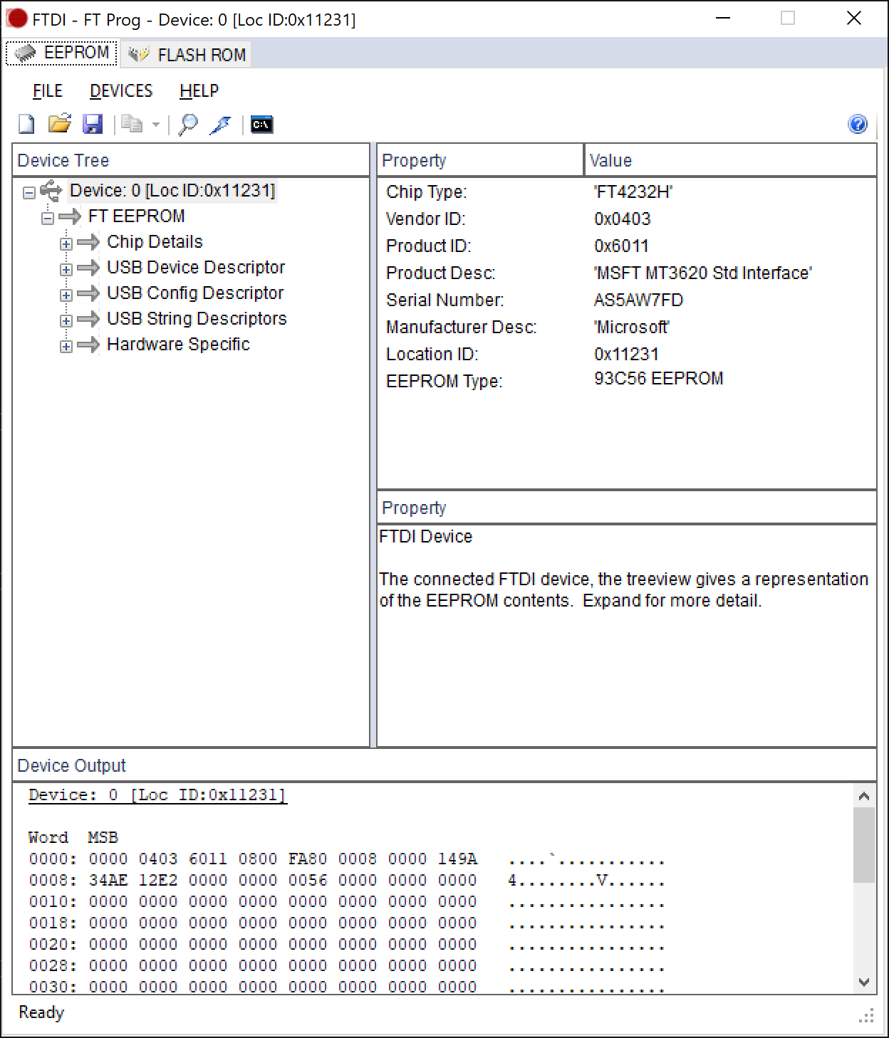
The following example shows the correct display:
See the FT_PROG documentation for more information about using the software.
Feedback
Coming soon: Throughout 2024 we will be phasing out GitHub Issues as the feedback mechanism for content and replacing it with a new feedback system. For more information see: https://aka.ms/ContentUserFeedback.
Submit and view feedback for