Configure Azure CNI Overlay networking in Azure Kubernetes Service (AKS)
The traditional Azure Container Networking Interface (CNI) assigns a VNet IP address to every pod. It assigns this IP address from a prereserved set of IPs on every node or a separate subnet reserved for pods. This approach requires IP address planning and could lead to address exhaustion, which introduces difficulties scaling your clusters as your application demands grow.
With Azure CNI Overlay, the cluster nodes are deployed into an Azure Virtual Network (VNet) subnet. Pods are assigned IP addresses from a private CIDR logically different from the VNet hosting the nodes. Pod and node traffic within the cluster use an Overlay network. Network Address Translation (NAT) uses the node's IP address to reach resources outside the cluster. This solution saves a significant amount of VNet IP addresses and enables you to scale your cluster to large sizes. An extra advantage is that you can reuse the private CIDR in different AKS clusters, which extends the IP space available for containerized applications in Azure Kubernetes Service (AKS).
Overview of Overlay networking
In Overlay networking, only the Kubernetes cluster nodes are assigned IPs from subnets. Pods receive IPs from a private CIDR provided at the time of cluster creation. Each node is assigned a /24 address space carved out from the same CIDR. Extra nodes created when you scale out a cluster automatically receive /24 address spaces from the same CIDR. Azure CNI assigns IPs to pods from this /24 space.
A separate routing domain is created in the Azure Networking stack for the pod's private CIDR space, which creates an Overlay network for direct communication between pods. There's no need to provision custom routes on the cluster subnet or use an encapsulation method to tunnel traffic between pods, which provides connectivity performance between pods on par with VMs in a VNet. Workloads running within the pods are not even aware that network address manipulation is happening.
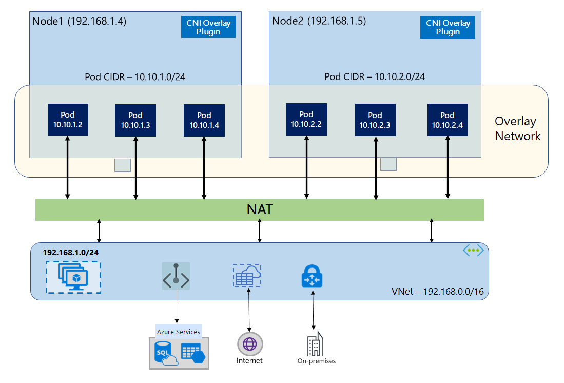
Communication with endpoints outside the cluster, such as on-premises and peered VNets, happens using the node IP through NAT. Azure CNI translates the source IP (Overlay IP of the pod) of the traffic to the primary IP address of the VM, which enables the Azure Networking stack to route the traffic to the destination. Endpoints outside the cluster can't connect to a pod directly. You have to publish the pod's application as a Kubernetes Load Balancer service to make it reachable on the VNet.
You can provide outbound (egress) connectivity to the internet for Overlay pods using a Standard SKU Load Balancer or Managed NAT Gateway. You can also control egress traffic by directing it to a firewall using User Defined Routes on the cluster subnet.
You can configure ingress connectivity to the cluster using an ingress controller, such as Nginx or HTTP application routing. You cannot configure ingress connectivity using Azure App Gateway. For details see Limitations with Azure CNI Overlay.
Differences between Kubenet and Azure CNI Overlay
Like Azure CNI Overlay, Kubenet assigns IP addresses to pods from an address space logically different from the VNet, but it has scaling and other limitations. The below table provides a detailed comparison between Kubenet and Azure CNI Overlay. If you don't want to assign VNet IP addresses to pods due to IP shortage, we recommend using Azure CNI Overlay.
| Area | Azure CNI Overlay | Kubenet |
|---|---|---|
| Cluster scale | 5000 nodes and 250 pods/node | 400 nodes and 250 pods/node |
| Network configuration | Simple - no extra configurations required for pod networking | Complex - requires route tables and UDRs on cluster subnet for pod networking |
| Pod connectivity performance | Performance on par with VMs in a VNet | Extra hop adds minor latency |
| Kubernetes Network Policies | Azure Network Policies, Calico, Cilium | Calico |
| OS platforms supported | Linux and Windows Server 2022, 2019 | Linux only |
IP address planning
- Cluster Nodes: When setting up your AKS cluster, make sure your VNet subnets have enough room to grow for future scaling. You can assign each node pool to a dedicated subnet. A
/24subnet can fit up to 251 nodes since the first three IP addresses are reserved for management tasks. - Pods: The Overlay solution assigns a
/24address space for pods on every node from the private CIDR that you specify during cluster creation. The/24size is fixed and can't be increased or decreased. You can run up to 250 pods on a node. When planning the pod address space, ensure the private CIDR is large enough to provide/24address spaces for new nodes to support future cluster expansion.- When planning IP address space for pods, consider the following factors:
- The same pod CIDR space can be used on multiple independent AKS clusters in the same VNet.
- Pod CIDR space must not overlap with the cluster subnet range.
- Pod CIDR space must not overlap with directly connected networks (like VNet peering, ExpressRoute, or VPN). If external traffic has source IPs in the podCIDR range, it needs translation to a non-overlapping IP via SNAT to communicate with the cluster.
- When planning IP address space for pods, consider the following factors:
- Kubernetes service address range: The size of the service address CIDR depends on the number of cluster services you plan to create. It must be smaller than
/12. This range shouldn't overlap with the pod CIDR range, cluster subnet range, and IP range used in peered VNets and on-premises networks. - Kubernetes DNS service IP address: This IP address is within the Kubernetes service address range that's used by cluster service discovery. Don't use the first IP address in your address range, as this address is used for the
kubernetes.default.svc.cluster.localaddress.
Network security groups
Pod to pod traffic with Azure CNI Overlay isn't encapsulated, and subnet network security group rules are applied. If the subnet NSG contains deny rules that would impact the pod CIDR traffic, make sure the following rules are in place to ensure proper cluster functionality (in addition to all AKS egress requirements):
- Traffic from the node CIDR to the node CIDR on all ports and protocols
- Traffic from the node CIDR to the pod CIDR on all ports and protocols (required for service traffic routing)
- Traffic from the pod CIDR to the pod CIDR on all ports and protocols (required for pod to pod and pod to service traffic, including DNS)
Traffic from a pod to any destination outside of the pod CIDR block utilizes SNAT to set the source IP to the IP of the node where the pod runs.
If you wish to restrict traffic between workloads in the cluster, we recommend using network policies.
Maximum pods per node
You can configure the maximum number of pods per node at the time of cluster creation or when you add a new node pool. The default for Azure CNI Overlay is 250. The maximum value you can specify in Azure CNI Overlay is 250, and the minimum value is 10. The maximum pods per node value configured during creation of a node pool applies to the nodes in that node pool only.
Choosing a network model to use
Azure CNI offers two IP addressing options for pods: The traditional configuration that assigns VNet IPs to pods and Overlay networking. The choice of which option to use for your AKS cluster is a balance between flexibility and advanced configuration needs. The following considerations help outline when each network model might be the most appropriate.
Use Overlay networking when:
- You would like to scale to a large number of pods, but have limited IP address space in your VNet.
- Most of the pod communication is within the cluster.
- You don't need advanced AKS features, such as virtual nodes.
Use the traditional VNet option when:
- You have available IP address space.
- Most of the pod communication is to resources outside of the cluster.
- Resources outside the cluster need to reach pods directly.
- You need AKS advanced features, such as virtual nodes.
Limitations with Azure CNI Overlay
Azure CNI Overlay has the following limitations:
- You can't use Application Gateway as an Ingress Controller (AGIC) for an Overlay cluster.
- Virtual Machine Availability Sets (VMAS) aren't supported for Overlay.
- You can't use DCsv2-series virtual machines in node pools. To meet Confidential Computing requirements, consider using DCasv5 or DCadsv5-series confidential VMs instead.
- In case you are using your own subnet to deploy the cluster, the names of the subnet, VNET and resource group which contains the VNET, must be 63 characters or less. This comes from the fact that these names will be used as labels in AKS worker nodes, and are therefore subjected to Kubernetes label syntax rules.
Set up Overlay clusters
Note
You must have CLI version 2.48.0 or later to use the --network-plugin-mode argument. For Windows, you must have the latest aks-preview Azure CLI extension installed and can follow the instructions below.
Create a cluster with Azure CNI Overlay using the az aks create command. Make sure to use the argument --network-plugin-mode to specify an overlay cluster. If the pod CIDR isn't specified, then AKS assigns a default space: viz. 10.244.0.0/16.
clusterName="myOverlayCluster"
resourceGroup="myResourceGroup"
location="westcentralus"

az aks create -n $clusterName -g $resourceGroup \
  --location $location \
  --network-plugin azure \
  --network-plugin-mode overlay \
  --pod-cidr 192.168.0.0/16
Add a new nodepool to a dedicated subnet
After you have created a cluster with Azure CNI Overlay, you can create another nodepool and assign the nodes to a new subnet of the same VNet. This approach can be useful if you want to control the ingress or egress IPs of the host from/ towards targets in the same VNET or peered VNets.
clusterName="myOverlayCluster"
resourceGroup="myResourceGroup"
location="westcentralus"
nodepoolName="newpool1"
subscriptionId=$(az account show --query id -o tsv)
vnetName="yourVnetName"
subnetName="yourNewSubnetName"
subnetResourceId="/subscriptions/$subscriptionId/resourceGroups/$resourceGroup/providers/Microsoft.Network/virtualNetworks/$vnetName/subnets/$subnetName"
az aks nodepool add  -g $resourceGroup --cluster-name $clusterName \
  --name $nodepoolName --node-count 1 \
  --mode system --vnet-subnet-id $subnetResourceId
Upgrade an existing cluster to CNI Overlay
Note
You can update an existing Azure CNI cluster to Overlay if the cluster meets the following criteria:
- The cluster is on Kubernetes version 1.22+.
- Doesn't use the dynamic pod IP allocation feature.
- Doesn't have network policies enabled. Network Policy engine can be uninstalled before the upgrade, see Uninstall Azure Network Policy Manager or Calico
- Doesn't use any Windows node pools with docker as the container runtime.
Note
Because Routing domain is not yet supported for ARM, CNI Overlay is not yet supported on ARM-based (ARM64) processor nodes.
Note
Upgrading an existing cluster to CNI Overlay is a non-reversible process.
Warning
Prior to Windows OS Build 20348.1668, there was a limitation around Windows Overlay pods incorrectly SNATing packets from host network pods, which had a more detrimental effect for clusters upgrading to Overlay. To avoid this issue, use Windows OS Build greater than or equal to 20348.1668.
Warning
If using a custom azure-ip-masq-agent config to include additional IP ranges that should not SNAT packets from pods, upgrading to Azure CNI Overlay can break connectivity to these ranges. Pod IPs from the overlay space will not be reachable by anything outside the cluster nodes.
Additionally, for sufficiently old clusters there might be a ConfigMap left over from a previous version of azure-ip-masq-agent. If this ConfigMap, named azure-ip-masq-agent-config, exists and is not intentionally in-place it should be deleted before running the update command.
If not using a custom ip-masq-agent config, only the azure-ip-masq-agent-config-reconciled ConfigMap should exist with respect to Azure ip-masq-agent ConfigMaps and this will be updated automatically during the upgrade process.
The upgrade process triggers each node pool to be re-imaged simultaneously. Upgrading each node pool separately to Overlay isn't supported. Any disruptions to cluster networking are similar to a node image upgrade or Kubernetes version upgrade where each node in a node pool is re-imaged.
Azure CNI Cluster Upgrade
Update an existing Azure CNI cluster to use Overlay using the az aks update command.
clusterName="myOverlayCluster"
resourceGroup="myResourceGroup"
location="westcentralus"

az aks update --name $clusterName \
--resource-group $resourceGroup \
--network-plugin-mode overlay \
--pod-cidr 192.168.0.0/16
The --pod-cidr parameter is required when upgrading from legacy CNI because the pods need to get IPs from a new overlay space, which doesn't overlap with the existing node subnet. The pod CIDR also can't overlap with any VNet address of the node pools. For example, if your VNet address is 10.0.0.0/8, and your nodes are in the subnet 10.240.0.0/16, the --pod-cidr can't overlap with 10.0.0.0/8 or the existing service CIDR on the cluster.
Kubenet Cluster Upgrade
Update an existing Kubenet cluster to use Azure CNI Overlay using the az aks update command.
clusterName="myOverlayCluster"
resourceGroup="myResourceGroup"
location="westcentralus"

az aks update --name $clusterName \
--resource-group $resourceGroup \
--network-plugin azure \
--network-plugin-mode overlay
Since the cluster is already using a private CIDR for pods which doesn't overlap with the VNet IP space, you don't need to specify the --pod-cidr parameter and the Pod CIDR will remain the same.
Note
When upgrading from Kubenet to CNI Overlay, the route table will no longer be required for pod routing. If the cluster is using a customer provided route table, the routes which were being used to direct pod traffic to the correct node will automatically be deleted during the migration operation. If the cluster is using a managed route table (the route table was created by AKS and lives in the node resource group) then that route table will be deleted as part of the migration.
Dual-stack Networking
You can deploy your AKS clusters in a dual-stack mode when using Overlay networking and a dual-stack Azure virtual network. In this configuration, nodes receive both an IPv4 and IPv6 address from the Azure virtual network subnet. Pods receive both an IPv4 and IPv6 address from a logically different address space to the Azure virtual network subnet of the nodes. Network address translation (NAT) is then configured so that the pods can reach resources on the Azure virtual network. The source IP address of the traffic is NAT'd to the node's primary IP address of the same family (IPv4 to IPv4 and IPv6 to IPv6).
Prerequisites
- You must have Azure CLI 2.48.0 or later installed.
- Kubernetes version 1.26.3 or greater.
Limitations
The following features aren't supported with dual-stack networking:
- Windows Nodepools
- Azure network policies
- Calico network policies
- NAT Gateway
- Virtual nodes add-on
Deploy a dual-stack AKS cluster
The following attributes are provided to support dual-stack clusters:
--ip-families: Takes a comma-separated list of IP families to enable on the cluster.- Only
ipv4oripv4,ipv6are supported.
- Only
--pod-cidrs: Takes a comma-separated list of CIDR notation IP ranges to assign pod IPs from.- The count and order of ranges in this list must match the value provided to
--ip-families. - If no values are supplied, the default value
10.244.0.0/16,fd12:3456:789a::/64is used.
- The count and order of ranges in this list must match the value provided to
--service-cidrs: Takes a comma-separated list of CIDR notation IP ranges to assign service IPs from.- The count and order of ranges in this list must match the value provided to
--ip-families. - If no values are supplied, the default value
10.0.0.0/16,fd12:3456:789a:1::/108is used. - The IPv6 subnet assigned to
--service-cidrscan be no larger than a /108.
- The count and order of ranges in this list must match the value provided to
Create a dual-stack AKS cluster
Create an Azure resource group for the cluster using the [
az group create][az-group-create] command.az group create -l <region> -n <resourceGroupName>Create a dual-stack AKS cluster using the
az aks createcommand with the--ip-familiesparameter set toipv4,ipv6.az aks create -l <region> -g <resourceGroupName> -n <clusterName> \ --network-plugin azure \ --network-plugin-mode overlay \ --ip-families ipv4,ipv6
Create an example workload
Once the cluster has been created, you can deploy your workloads. This article walks you through an example workload deployment of an NGINX web server.
Deploy an NGINX web server
The application routing addon is the recommended way for ingress in an AKS cluster. For more information about the application routing addon and an example of how to deploy an application with the addon, see Managed NGINX ingress with the application routing add-on.
Expose the workload via a LoadBalancer type service
Important
There are currently two limitations pertaining to IPv6 services in AKS.
- Azure Load Balancer sends health probes to IPv6 destinations from a link-local address. In Azure Linux node pools, this traffic can't be routed to a pod, so traffic flowing to IPv6 services deployed with
externalTrafficPolicy: Clusterfail. IPv6 services must be deployed withexternalTrafficPolicy: Local, which causeskube-proxyto respond to the probe on the node. - Prior to Kubernetes version 1.27, only the first IP address for a service will be provisioned to the load balancer, so a dual-stack service only receives a public IP for its first-listed IP family. To provide a dual-stack service for a single deployment, please create two services targeting the same selector, one for IPv4 and one for IPv6. This is no longer a limitation in kubernetes 1.27 or later.
Expose the NGINX deployment using the
kubectl expose deployment nginxcommand.kubectl expose deployment nginx --name=nginx-ipv4 --port=80 --type=LoadBalancer' kubectl expose deployment nginx --name=nginx-ipv6 --port=80 --type=LoadBalancer --overrides='{"spec":{"ipFamilies": ["IPv6"]}}'You receive an output that shows the services have been exposed.
service/nginx-ipv4 exposed
service/nginx-ipv6 exposed
Once the deployment is exposed and the
LoadBalancerservices are fully provisioned, get the IP addresses of the services using thekubectl get servicescommand.kubectl get servicesNAME TYPE CLUSTER-IP EXTERNAL-IP PORT(S) AGE nginx-ipv4 LoadBalancer 10.0.88.78 20.46.24.24 80:30652/TCP 97s nginx-ipv6 LoadBalancer fd12:3456:789a:1::981a 2603:1030:8:5::2d 80:32002/TCP 63sVerify functionality via a command-line web request from an IPv6 capable host. Azure Cloud Shell isn't IPv6 capable.
SERVICE_IP=$(kubectl get services nginx-ipv6 -o jsonpath='{.status.loadBalancer.ingress[0].ip}')
curl -s "http://[${SERVICE_IP}]" | head -n5
<!DOCTYPE html> <html> <head> <title>Welcome to nginx!</title> <style>
Next steps
To learn how to utilize AKS with your own Container Network Interface (CNI) plugin, see Bring your own Container Network Interface (CNI) plugin.
Feedback
Coming soon: Throughout 2024 we will be phasing out GitHub Issues as the feedback mechanism for content and replacing it with a new feedback system. For more information see: https://aka.ms/ContentUserFeedback.
Submit and view feedback for