Call flow topologies
This article describes Azure Communication Services call flow topologies. Within this article, you learn details about network concepts for Azure Communication Services, how calling traffic is encrypted, and For an introduction to Communication Services call flows, visit the call flows conceptual documentation.
Background
Network concepts
Before reviewing call flow topologies, we define some terms that are referred to throughout the document.
A customer network contains any network segments that you manage. This might include wired and wireless networks within your office or between offices, data centers, and internet service providers.
A customer network usually has several network perimeters with firewalls and/or proxy servers that enforce your organization's security policies. We recommend performing a comprehensive network assessment to ensure optimal performance and quality of your communication solution.
The Communication Services network is the network that supports Azure Communication Services. This network is managed by Microsoft and is distributed worldwide with Microsoft owned data centers closest to end customers. This network is responsible for transport relay, media processing for group calls, and other components that support rich real-time media communications.
Types of traffic
Communication Services is built primarily on two types of traffic: real-time media and signaling.
Real-time media is transmitted using the Real-time Transport Protocol (RTP). This protocol supports audio, video, and screen sharing data transmission. This data is sensitive to network latency issues. While it's possible to transmit real-time media using TCP or HTTP, we recommend using UDP as the transport-layer protocol to support high-performance end-user experiences. Media payloads transmitted over RTP are secured using SRTP.
Users of your Communication Services solution are connecting to your services from their client devices. Communication between these devices and your servers is handled with signaling. For example: call initiation and real-time chat are supported by signaling between devices and your service. Most signaling traffic uses HTTPS REST, though in some scenarios, SIP can be used as a signaling traffic protocol. While this type of traffic is less sensitive to latency, low-latency signaling give the users of your solution a pleasant end-user experience.
Media Encryption
Call flows in Azure Communication Services calling SDK and Teams clients are based on the Session Description Protocol (SDP) RFC 8866 offer and answer model over HTTPS. Once the callee accepts an incoming call, the caller and callee agree on the session parameters.
Media traffic is encrypted, and flows between, the caller and callee using Secure RTP (SRTP), a profile of Real-time Transport Protocol (RTP) that provides confidentiality, authentication, and replay attack protection to RTP traffic. In most cases, client to client media traffic is negotiated through client to server connection signaling, and is encrypted using SRTP when going directly from client to client.
Azure Communication Services calling SDK use DTLS to derive an encryption key. Once the DTLS handshake is done, the media begins to flow using this DTLS-negotiated encryption key over SRTP.
Azure Communication Services calling SDK and Teams clients uses a credentials-based token for secure access to media relays over TURN. Media relays exchange the token over a TLS-secured channel.
Azure Communication Services media traffic between two endpoints participating in Azure Communication Services audio, video, and video sharing utilizes SRTP to encrypt the media stream. Cryptographic keys are negotiated between the two endpoints over a signaling protocol, which uses TLS 1.2 and AES-256 (in GCM mode) encrypted UDP/TCP channel.
Call flow principles
There are four general principles that underpin Azure Communication Services call flows:
- The first participant of a Communication Services group call determines the region in which the call is hosted. There are exceptions to this rule in some topologies, which are described below.
- The media endpoint used to support a Communication Services call is selected based on media processing needs, and isn't affected by the number of participants on a call. For example, a point-to-point call may use a media endpoint in the cloud to process media for transcription or recording, while a call with two participants may not use any media endpoints. Group calls use a media endpoint for mixing and routing purposes. This endpoint is selected based on the region in which the call is hosted. Media traffic sent from a client to the media endpoint may be routed directly or it may use a transport relay in Azure if customer network firewall restrictions require it.
- Media traffic for peer-to-peer calls takes the most direct route that's available, assuming the call doesn't need a media endpoint in the cloud. The preferred route is direct to the remote peer (client). If a direct route isn't available, one or more transport relays forward the traffic. Media traffic shouldn't transverse servers that act like packet shapers, VPN servers, or other functions that might delay processing and degrade the end-user experience.
- Signaling traffic always goes to whatever server is closest to the user.
To learn more about the details on the media path that is chosen, refer to the call flows conceptual documentation.
Call flows in various topologies
Communication Services (internet)
This topology is used by customers that use Communication Services from the cloud without any on-premises deployment, such as Azure direct routing. In this topology, traffic to and from Communication Services flows over the Internet.

Figure 1 - Communication Services topology
The direction of the arrows on the above diagram reflects the initiation direction of the communication that affects connectivity at the enterprise perimeters. In the case of UDP for media, the first packets may flow in the reverse direction, but these packets may be blocked until packets in the other direction are flowing.
Flow descriptions:
- Flow 2 – Represents a flow initiated by a user on the customer network to the Internet as a part of the user's Communication Services experience. Examples of these flows include DNS and peer-to-peer media transmission.
- Flow 2` – Represents a flow initiated by a remote mobile Communication Services user, with VPN to the customer network.
- Flow 3 – Represents a flow initiated by a remote mobile Communication Services user to Communication Services endpoints.
- Flow 4 – Represents a flow initiated by a user on the customer network to Communication Services.
- Flow 5 – Represents a peer-to-peer media flow between one Communication Services user and another within the customer network.
- Flow 6 – Represents a peer-to-peer media flow between a remote mobile Communication Services user and another remote mobile Communication Services user over the Internet.
Use case: One-to-one calling
A One-to-one call means one user directly calls another user. In order to initialize the call the calling SDK obtain a set of candidates consisting of IP addresses and ports, including local, relay, and reflexive (public IP address of client as seen by the relay) candidates. The caller SDK sends these candidates to the called party; the called party also obtains a similar set of candidates and sends them to the caller. STUN connectivity check messages are used to find which caller/called party media paths work, and the best working path is selected. Once the connection path is established, a DTLS handshake is performed over this connection to ensure the security. After the DTLS handshake, the SRTP keys are derived from the DTLS handshake process. Media (that is, RTP/RTCP packets secured using SRTP) are then sent using the selected candidate pair. The transport relay is available as part of Azure Communication Services.
If the local IP address and port candidates or the reflexive candidates have connectivity, then the direct path between the clients (or using a NAT) are selected for media. If the clients are both on the customer network, then the direct path should be selected. This requires direct UDP connectivity within the customer network. If the clients are both nomadic cloud users, then depending on the NAT/firewall, media may use direct connectivity.
If one client is internal on the customer network and one client is external (for example, a mobile cloud user), then it's unlikely that direct connectivity between the local or reflexive candidates would be enabled. In this case, an option is to use one of the transport relay candidates from either client (for example, the internal client obtained a relay candidate from the transport relay in Azure; the external client needs to be able to send STUN/RTP/RTCP packets to the transport relay). Another option is the internal client sends to the relay candidate obtained by the mobile cloud client. Although UDP connectivity for media is highly recommended, TCP is supported.
High-level steps:
- Communication Services User A resolves URL domain name (DNS) using Flow 2.
- User A allocates a media relay port on the Teams transport relay using Flow 4.
- Communication Services User A sends an "invite" with ICE candidates using Flow 4 to Communication Services.
- Communication Services notifies User B using Flow 4.
- User B allocates a media relay port on Teams transport relay using Flow 4.
- User B sends "answer" with ICE candidates using Flow 4, which is forwarded back to User A using Flow 4.
- User A and User B invoke ICE connectivity tests and the best available media path is selected (see diagrams below for various use cases).
- Both users send telemetry to Communication Services using Flow 4.
Customer network (intranet)
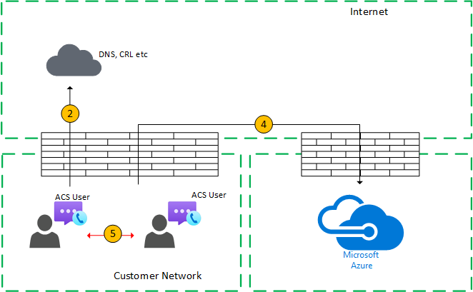
Figure 2 - Within customer network
In Step 7, peer-to-peer media Flow 5 is selected.
This media transmission is bidirectional. The direction of Flow 5 indicates that one side initiates the communication from a connectivity perspective. In this case, it doesn't matter which direction is used because both endpoints are within the customer network.
Customer network to external user (media relayed by Teams Transport Relay)
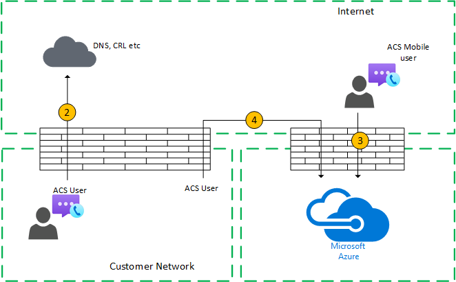
Figure 3 - Customer network to external user (media relayed by Azure Transport Relay)
In Step 7, Flow 4 (from the customer network to Communication Services) and Flow 3 (from a remote mobile Communication Services user to Azure Communication Services) are selected.
These flows are relayed by Teams Transport Relay within Azure.
This media transmission is bidirectional. The direction indicates which side initiates the communication from a connectivity perspective. In this case, these flows are used for signaling and media, using different transport protocols and addresses.
Customer network to external user (direct media)
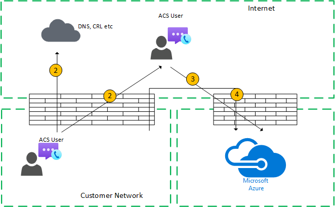
Figure 4 - Customer network to external user (direct media)
In step 7, Flow 2 (from customer network to the client's peer over the Internet) is selected.
Direct media with a remote mobile user (not relayed through Azure) is optional. In other words, you can block this path to enforce a media path through a transport relay in Azure.
This media transmission is bidirectional. The direction of Flow 2 to remote mobile user indicates that one side initiates the communication from a connectivity perspective.
VPN user to internal user (media relayed by Teams Transport Relay)
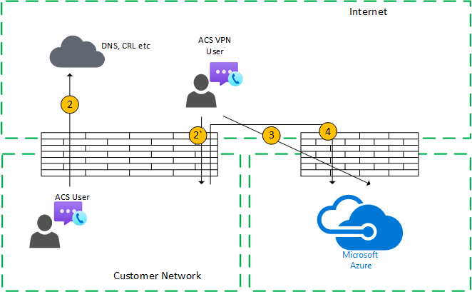
Figure 5 - VPN user to internal user (media relayed by Azure Relay
Signaling between the VPN to the customer network uses Flow 2*. Signaling between the customer network and Azure uses Flow 4. However, media bypasses the VPN and is routed using Flows 3 and 4 through Azure Media Relay.
VPN user to internal user (direct media)
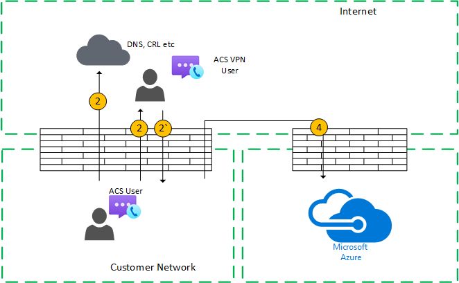
Figure 6 - VPN user to internal user (direct media)
Signaling between the VPN to the customer network uses Flow 2'. Signaling between the customer network and Azure is using flow 4. However, media bypasses the VPN and is routed using flow 2 from the customer network to the Internet.
This media transmission is bidirectional. The direction of Flow 2 to the remote mobile user indicates that one side initiates the communication from a connectivity perspective.
VPN user to external user (direct media)
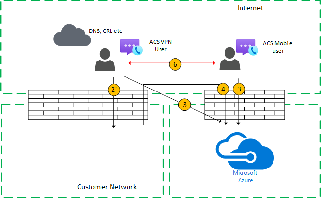
Figure 7 - VPN user to external user (direct media)
Signaling between the VPN user to the customer network uses Flow 2* and Flow 4 to Azure. However, media bypasses VPN and is routed using Flow 6.
This media transmission is bidirectional. The direction of Flow 6 to the remote mobile user indicates that one side initiates the communication from a connectivity perspective.
Use Case: Communication Services client to PSTN through Communication Services Trunk
Communication Services allows placing and receiving calls from the Public Switched Telephone Network (PSTN). If the PSTN trunk is connected using phone numbers provided by Communication Services, there are no special connectivity requirements for this use case. If you want to connect your own on-premises PSTN trunk to Azure Communication Services, you can use Azure direct routing (available in CY2021).

Figure 8 – Communication Services User to PSTN through Azure Trunk
In this case, signaling and media from the customer network to Azure use Flow 4.
Use case: Communication Services group calls
The audio/video/screen sharing (VBSS) service is part of Azure Communication Services. It has a public IP address that must be reachable from the customer network and must be reachable from a Nomadic Cloud client. Each client/endpoint needs to be able to connect to the service.
Internal clients obtain local, reflexive, and relay candidates in the same manner as described for one-to-one calls. The clients send these candidates to the service in an invite. The service doesn't use a relay since it has a publicly reachable IP address, so it responds with its local IP address candidate. The client and the service check connectivity in the same manner described for one-to-one calls.
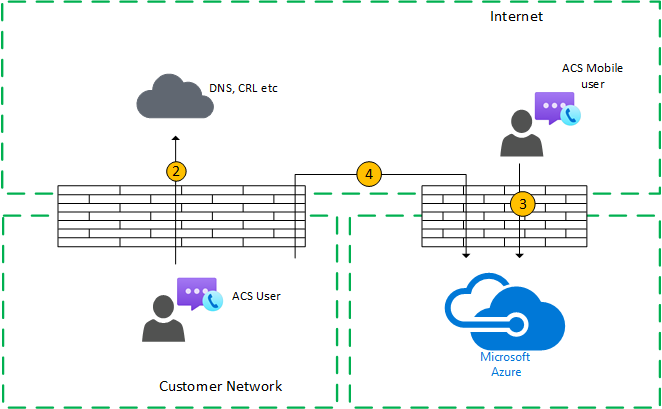
Figure 9 – Communication Services Group Calls
Interoperability restrictions
Media flowing through Azure Communication Services is restricted as follows:
Third-party Session Border Controller (SBC) on the boundary with PSTN should terminate the RTP/RTCP stream, secured using SRTP, and not relay it to the next hop. If you relay the flow to the next hop, it might not be understood.
Third-party SIP proxy servers. A Communication Services signaling SIP dialog with a third-party SBC and/or gateway may traverse Microsoft native SIP proxies (just like Teams). Interoperability with third-party SIP proxies isn't supported.
Third-party B2BUA (or SBC). Communication Services media flow to and from the PSTN is terminated by a third-party SBC. Interoperability with a third-party SBC within the Communication Services network (where a third-party SBC mediates two Communication Services endpoints) isn't supported.
Unsupported technologies
VPN network. Communication Services doesn't support media transmission over VPNs. If your users are using VPN clients, the client should split and route media traffic over a non-VPN connection as specified in Enabling Lync media to bypass a VPN tunnel.
Note
Although the title indicates Lync, it is applicable to Azure Communication Services and Teams.*
Packet shapers. Packet snipping, packet inspection, or packet shaping devices are not supported and may degrade quality significantly.
Next steps
The following documents may be interesting to you:
- Learn more about call types
- Learn about Client-server architecture
Feedback
Coming soon: Throughout 2024 we will be phasing out GitHub Issues as the feedback mechanism for content and replacing it with a new feedback system. For more information see: https://aka.ms/ContentUserFeedback.
Submit and view feedback for