Build Connected Field Service processes and automations
Dynamics 365's Connected Field Service solution lets you remotely monitor IoT enabled devices to keep track of up time, device statistics, anomalies and more. After an IoT Device communicates an anomaly or exception, that information is sent to Connected Field Service as an alert. Once the alert is captured, we can use Dynamics 365's ability to create automation and business process to develop automated processes for acting on, routing, and fixing the issues.
The purpose of this hands-on-lab is to introduce you to building and automating Connected Field Service processes, and demonstrate how these items can be used as part of an overall IoT solution.
Scenario
You work for a plumbing and heating company that sells and services smart home devices. Since many of the devices that you service are smart devices, information from those devices can be captured remotely to aid in the servicing of that equipment. Your organization has several defined scenarios and processes that they use while servicing equipment. These processes can vary depending on several factors including:
Type of device in need of service
Severity of the issue detected
Age of the device
Location of the device
Availability of resources to work on a specific device
The above items represent only a small portion of factors that your organization uses to determine the process for servicing equipment.
Lately, you have been installing many smart thermostat devices. These devices have been handy in being able to track temperature and humidity readings in areas when it's important to maintain a consistent temperature and humidity. Now because you have more information available, it has forced you to create new processes for handling and resolving issues reported by these devices. The first area you would like to focus on automating is the process used for temperature related issues.
Your organization is looking to implement the following process:
If a device detects a temperature reading of more than 70 degrees, an alert should be surfaced in your Connected Field Service environment.
If the temperature reading is between 70 degrees and 85 degrees, a command should be sent to remotely reset the device to see if the issue resolves itself.
If the temperature reading is between 86 degrees and 100 degrees, a service agent should be able to create a case to attempt to resolve the issue.
- If the service agent can't resolve the issue, a work order should be created, and an on-site technician should be scheduled for the item.
If the temperature reading is more than 100 degrees, it's considered a potentially catastrophic event. A work order should be created, and an on-site technician should be scheduled for the item.
Exercise - Automate and customize
Before you begin: This exercise assumes that you already have a working Connected Field Service deployment that is connected to either an Azure IoT Hub or an IoT Central instance. If you don't have a Connected Field Service environment available, it's recommended that you take the Introduction to Connect Field Service Module. That module helps you to set up and configure a Connected Field Service environment.
Task - Create a new IoT alert process solution
In this first task, we create a Dynamics 365 solution that we can use for storing all the customizations and processes that we create in this module. Not only does this make it easier for us to potentially transport these customizations later, but it also helps with cleaning up our environments after you complete the course.
Navigate to Power Apps and make sure you are in the correct environment.
Select Solutions and select New Solution.
Name the solution IoT Alert Processes.
Select the Publisher drop down and select Publisher.
Configure the Publisher as follows.
Display Name: Connected Field Service Course
Name: Connected Field Service Course
Prefix: cfs
Select Save.
Select the Publisher dropdown and select the publisher you created.
In the Version field, enter 1.0.0.0. and select Create.
Select to open the IoT Alert Process solution you created.
Select Add Exiting and select Table.
Select the Case, IoT Alert, and Work Order and then select Next.
Select Include All Objects for all three tables and select Add.
Task - Customize the IoT alert table
To help with automating items and actions based on IoT alerts, we need to be able to extract specific information for generated IoT alerts. We can query it and trigger items based on that data. Since the alert data contains only a JSON string that contains all the data, we need to create some other fields on the IoT alert table. We can use it to send specific data into and build queries off those fields.
Make sure you're still in the IoT Alert Processes solution.
Select to open the IoT Alert table.
Select the Columns tab and select New Column.
Enter Reading for Display Name, select Whole Number for Data Type, and select Advanced Options.
Enter 0 for Minimum Value, 250 for Maximum Value, and select Save.
Repeat the process to add these columns:
Threshold
Display Name: Threshold
Data Type: Whole Number
Minimum Value: 0
Maximum Value: 250
Reading Type
Display Name: Reading Type
Data Type: Yes/No
Change the No value to Temperature
Change the Yes value to Humidity
Default choice: Temperature
Rule Output
Display Name: Rule Output
Data Type: Single Line of Text
Customer
Display Name: Customer
Data Type: Lookup
Target Record Type: Account
Using the breadcrumbs, select IoT Alert.
Select Relationships under Schema.
Select New Relationship and select One-to-Many.
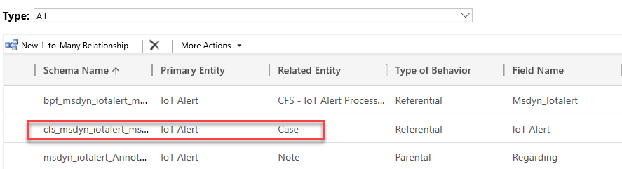
Select Case for the Related Entity, enter IoT Alert for Lookup Column Display Name, and select Done.
Select the solutions name.
Select Publish all customizations and wait for the publishing to complete.
Select the ... button and select Switch to classic.
Expand Entities, expand the IoT Alert entity, and select 1: N Relationships.
Select Mappings and select New.
Configure the mapping from the list as follows and select OK.
Source Entity Field: cfs_customer
Target Entity Field: customerid
Select Save and Close.
Select Publish all customizations and wait for the publishing to complete.
Close the solution explorer.

Task - Create a flow to populate values
Now that we have the field available to store the data that we need, we next need to populate those fields with the correct data. To do so, we're using some of the JSON-based field value actions that are included in the Connected Field Service solution. We create a flow that executes a JSON-based field value action, to extract a specific piece of data from the alert data field. Then we populate that data to one of the fields we created in the previous task.
Navigate to Power Apps and make sure you are in the correct environment.
Select Solutions and select to open the IoT Alert Processes solution.
Select New and select Automation > Cloud Flow > Automated.
Set the Flow Name to Populate Alert Fields.
Search for Microsoft Dataverse and select Dataverse. Make sure that you have selected the Green Dataverse Connector.
Select When a Record is Created, Updated, or Deleted, then select the Create button.
Select Added for Trigger Condition, IoT Alerts for Table Name, select Organization for Scope and select New Step.
Search for Parse and select Parse Json.
Select the Content field and select Alert Data from the Dynamic Content pane.
Paste this Json schema in the Schema field and select + New Step.
{
    "type": "object",
    "properties": {
        "deviceid": {
            "type": "string"
        },
        "readingtype": {
            "type": "string"
        },
        "reading": {
            "type": "integer"
        },
        "eventtoken": {
            "type": "string"
        },
        "threshold": {
            "type": "integer"
        },
        "ruleoutput": {
            "type": "string"
        },
        "time": {
            "type": "string"
        }
    }
}
Search for Update a Row and select Update a Row. Make sure that you have selected Green Dataverse Connector.
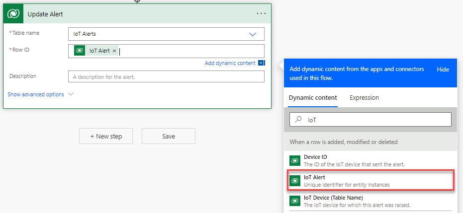
Rename the step Update Alert.
Select IoT Alerts for Entity Name, select the Row ID field and select IoT Alert from the Dynamic Content pane.
Select Show Advanced Options.
Select the Reading field and select reading of the Parse Json step in the Dynamic Content.

Select the Reading Type field and select Enter Custom Value.
Select the Expression tab, paste this expression, and select OK. Make sure Parse_JSON matches the Parse Json step name.
if(equals(body('Parse_JSON')?['readingtype'], 'Temperature'), false, true)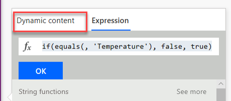
Select the Rule Output field and select ruleoutput from the Parse JSON action in Dynamic Content pane.
Select the Threshold field and select threshold from the Parse JSON action in Dynamic Content pane.
Your completed Flow should resemble this image:
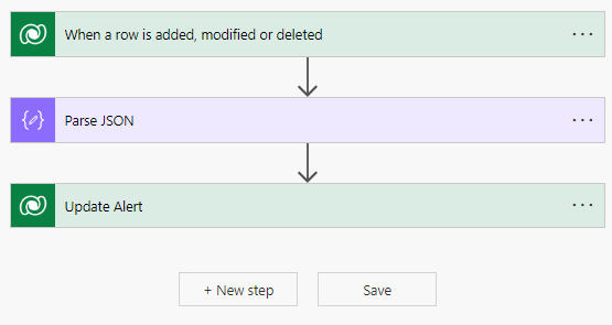
Select Save.
DO NOT close this page.


Task - Add the remote reset flow steps
Now that we have extracted the correct data and placed it in the correct fields, we need to add new steps to the flow. These steps determine the temperature value in the reading field. If it falls between 71 degrees and 85 degrees, it should automatically create an IoT device command that performs a device reset, and send it to the device.
Go back to the flow and select New Step.
Select Condition.
Select the Choose Value field and select Reading from the Update Alert step in the Dynamic content.

Select is greater than or equal to.
Enter 71 for Value, select Add, and select Add row.
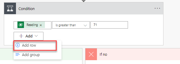
Select the Choose Value field and select Reading from the Update Alert step in the Dynamic Content.
Select Is Less than or Equal to.
Enter 85 for Value.
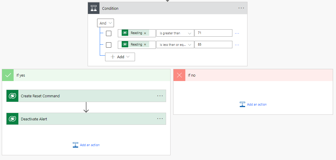
Your condition should now look like this image.

Go to the Yes branch and select Add an Action.
Search for Add a new row and select Add a new row.
Rename the step Create Reset Command.
Select IoT Device Commands for Table Name, select the Name field and select Description from the When a record is created, updated or deleted action in the dynamic content.
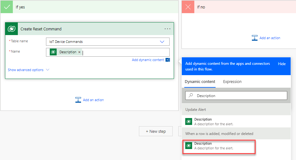
Add Device Reset to the Name and select Show Advanced Options.
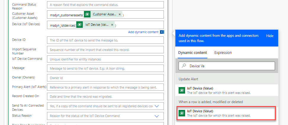
Select the Customer Asset field and type msdyn_customerassets().
Place your cursor between ( and ) and select Customer Assets (Value) from the When a record is created, updated or deleted action in the dynamic content.

Select the Device field and type msdyn_iotdevices().
Place your cursor between ( and ) and select IoT Device (Value) from the When a record is created, updated or deleted action in the dynamic content.
Select the Primary Alert field and type msdyn_iotalerts().
Place your cursor between ( and ) and select IoT Alert from the Update Alert action in the dynamic content.

Paste this JSON in the Message field.
{"CommandName":"Reset Thermostat","Parameters":{}}
Select Hide Advanced Options.
Select Add an Action.
Search for Update a Row and select Update a Row.
Rename the step Deactivate Alert.
Select IoT Alerts for Table Name, select the Record ID field and select IoT Alert from the Update Alert action in the Dynamic Content.

Select Show Advanced Options.
Locate the Status field and set it to Inactive.
Select Hide Advanced Options.
The new part of the flow should now look like the image.
Select Save.


Task - Modify the CFS - IoT alert process flow
Currently we're using a business process flow called CFS - IoT Alert Process Flow to guide users in resolving an alert when it's triggered. When a temperature reading is between 86 degrees and 100 degrees, in the business process we should create a case record. Then create a work order if we can't resolve the case. If the temperature reading is above 100 degrees, the business process should skip the case stage all together and go straight to work order. In this task, we're modifying the CFS - IoT Alert Process Flow to reflect these specific needs.
Navigate to Power Apps and make sure you are in the correct environment.
Select Solutions and select to open the IoT Alert Processes solution.
Select Add Existing and select Automation > Process.
Search for CFS, select CFS - IoT Alert Process Flow and select Add.
Open the CFS - IoT Alert Process Flow.
Select the Deactivate button to deactivate the process.
Confirm deactivation.
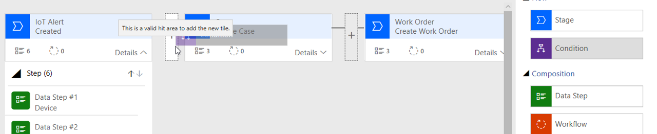
Expand Details on the IoT Alert Created stage.

Under Components, drag the Data Step below the Alert Time step.
Configure the Data Step as follows:
Step Name: Reading
Data Field: Reading
Select Apply to save your changes.
Repeat steps 9 - 11 to add the following Data Steps to the IoT Alert Created stage:
Threshold
Reading Type
Rule Output
Select the Components tab, drag the Condition component to the right of the IoT Alert Created stage.
In the Condition Display Name, enter Temperature Condition.
Configure Rule 1 as follows:
Field: Reading
Operator: Is greater than or equal to
Type: Value
Value: 86
Select the New button to add another rule.
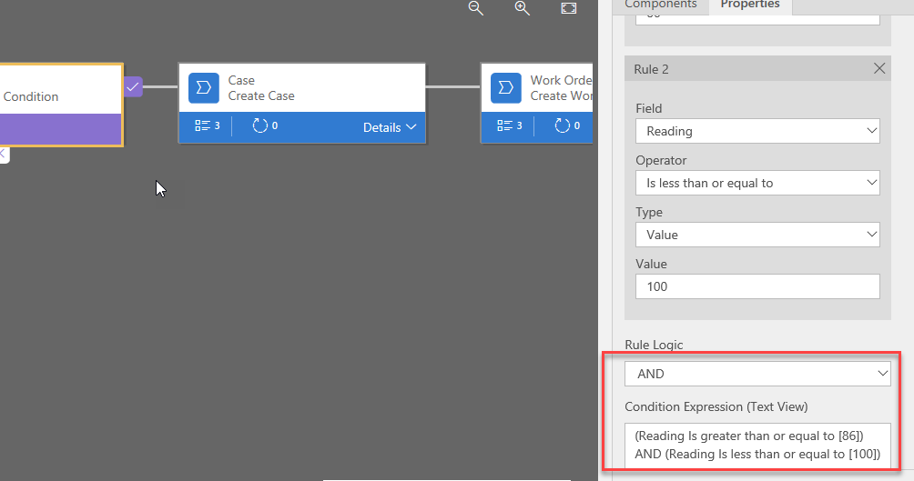
Configure Rule 2 as follows:
Field: Reading
Operator: Is less than or equal to
Type: Value
Value: 100
Ensure the Rule Logic is set to And.
Select Apply
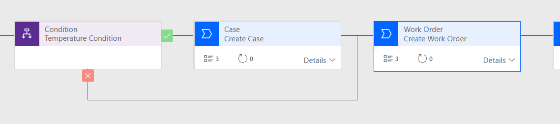
Select the Temperature Condition Stage, select the Connector Icon, from the menu that appears, select Reconnect.
Select the Create Work Order stage as the 2nd Point.
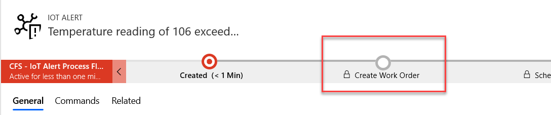
Your business process flow should now resemble the image:
Select Save and Activate the CFS - IoT Alert Process Flow.
Close the Process editor browser window or tab.
Select Done on the previous window for the Solution.
Select Solutions and select Publish All Customizations.


Task - Test your newly created automation
Now that we can create the necessary customizations, flow, and business process flows we use a simulator to test everything to ensure that it's performing the desired functionality.
Navigate to Power Apps and make sure you are in the correct environment.
Select Customer Assets and select the New Button.
Enter Start Thermostat for Name, select Adventure Works for Account and select Save.
Locate the Device ID field, enter smt-9876 and Save.
Select Register Devices.
Select OK.
In your web browser, select a new tab and navigate to Azure portal (Log into Azure if prompted. You need an Azure subscription associated with the account you're using).
Select Resource Groups and open your resource group.
Open the IoT Hub that you're using with Connected Field Service, and select the Simulator
Select the Simulator URL to open the Thermostat Simulator (The simulator should open in a new tab).
On the simulator, select Connection.
Switch back to your Azure subscription, close the simulator App Service screen.
Open the IoT Hub.
Highlight the IoT Hub name and Copy it.
Switch back to your simulator screen and paste the IoT hub name into the Host field.
Switch back to your Azure subscription, select Shared Access Policies.
Open the iothubowner policy and copy the Primary key.

Switch back to your simulator screen and paste the Primary key into the Key field.
Select the Connect button.
Select the Refresh button to ensure all registered devices are available.
From the Select a device drop down, select the smt-9876 device. (A green dot should appear next to the Refresh button, and after a few seconds it should start transmitting information.)

On the Temperature Slider, set it to 75 Degrees and wait for the temperature status to register on in the Messages Sent window.
Because the temperature was between 71 degrees and 85 degrees, a command is sent to the device to reboot it. (It can take several minutes for the reboot command to be sent to the device, depending on the internet speed.)
Switch to the browser tab that has Connected Field Service loaded.
Select IoT Alerts.
Switch the view to Inactive IoT Alerts.
Open the Temperature of 75 exceeded a threshold of 70 Alert.
Select the Commands tab. (You should see a command that was sent to the device.)

Switch back to the web browser tab that contains your Simulator.
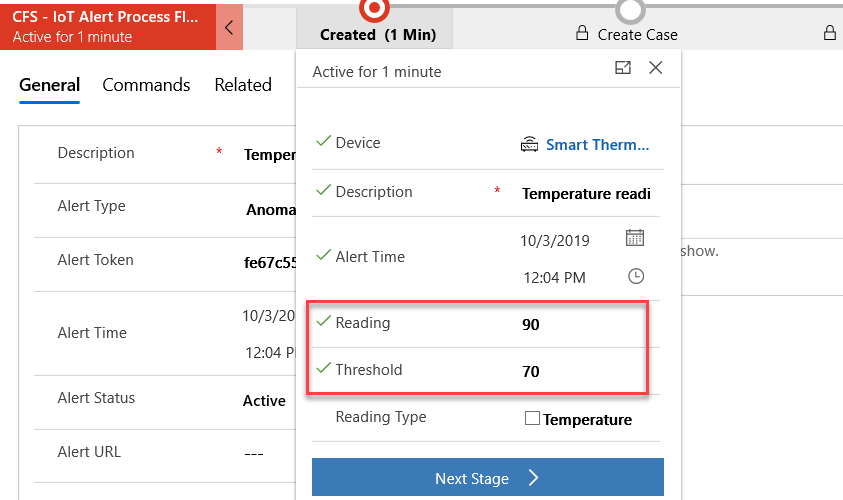
Set the Temperature to 90 Degrees and wait for it to register in the Messages Sent window.
Switch to the browser tab that has Connected Field Service loaded.
Select IoT Alerts.
Open the Temperature reading of 90 exceeded a threshold of 70 alert.
Select the Created Stage. (Notice the information we extracted earlier is being displayed, and because the reading is between 86 and 100, create case it the next stage.)
On the Menu select Send Command.
Select Switch to Json.
Enter the below code for the Command and select Send.
{"CommandName":"Reset Thermostat","Parameters":{}}Switch back to your Simulator and wait for the device to Reboot.
On the Temperature Slider, set it to 106 Degrees and wait for the temperature status to register on in the Messages Sent window.
Switch to the browser tab that has Connected Field Service loaded.
Select IoT Alerts.
Open the temperature reading of 106 exceeded a threshold of 70 alert.
Notice because the alert was above 100 degrees, that it skipped the Create Case stage completely.