Get Started with Domain-Specific Languages
This topic explains the basic concepts in defining and using a domain-specific language (DSL) created with the Modeling SDK for Visual Studio.
Note
The Text Template Transformation SDK and the Visual Studio Modeling SDK are installed automatically when you install specific features of Visual Studio. For more details, see this blog post.
If you are new to DSLs, we recommend that you work through the DSL Tools Lab, which you can find in this site: Visualization and Modeling SDK
What can you do with a Domain-Specific Language?
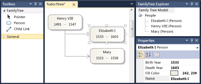
A domain-specific language is a notation, usually graphical, that is designed to be used for a particular purpose. By contrast, languages such as UML are general-purpose. In a DSL, you can define the types of model element and their relationships, and how they are presented on the screen.
When you have designed a DSL, you can distribute it as part of a Visual Studio Integration Extension (VSIX) package. Users work with the DSL in Visual Studio:
The notation is only part of a DSL. Together with the notation, your VSIX package includes tools that users can apply to help them edit and generate material from their models.
One of the principal applications of DSLs is to generate program code, configuration files, and other artifacts. Especially in large projects and product lines, where several variants of a product will be created, generating many of the variable aspects from DSLs can provide a large increase in reliability and a very rapid response to requirements changes.
The rest of this overview is a walkthrough that introduces the basic operations of creating and using a domain-specific language in Visual Studio.
Prerequisites
To define a DSL, you must have installed the following components:
| Component | Link |
|---|---|
| Visual Studio | http://go.microsoft.com/fwlink/?LinkId=185579 |
| Visual Studio SDK | https://go.microsoft.com/fwlink/?linkid=2166172 |
| Modeling SDK for Visual Studio |
Note
The Text Template Transformation component is automatically installed as part of the Visual Studio extension development workload. You can also install it from the Individual components tab of Visual Studio Installer, under the SDKs, libraries, and frameworks category. Install the Modeling SDK component from the Individual components tab.
Create a DSL Solution
To create a new domain-specific language, you create a new Visual Studio solution by using the Domain-Specific Language project template.
On the File menu, point to New, and then click Project.
Under Project types, expand the Other Project Types node, and click Extensibility.
Click Domain-Specific Language Designer.
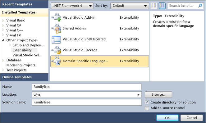
In the Name box, type FamilyTree. Click OK.
The Domain-Specific Language Wizard opens, and displays a list of template DSL solutions.
Click each template to see a description,
The templates are useful starting points. Each of them provides a complete working DSL, which you can edit to suit your needs. Ordinarily, you would choose the template nearest what you want to create.
For this walkthrough, choose the Minimal Language template.
Enter a file name extension for your DSL in the appropriate wizard page. This is the extension that files containing instances of your DSL will use.
Choose an extension that is not associated with any application in your computer, or in any computer where you want to install the DSL. For example, docx and htm would be unacceptable file name extensions.
The wizard will warn you if the extension that you have entered is being used as a DSL. Consider using a different file name extension. You can also reset the Visual Studio SDK Experimental instance to clear out old experimental designers. In the Windows Start menu, type reset the Visual Studio, and then run the Reset the Microsoft Visual Studio Experimental Instance command matching your version of Visual Studio.
Inspect the other pages and then click Finish.
A solution is generated that contains two projects. They are named Dsl and DslPackage. A diagram file opens that is named DslDefinition.dsl.
Note
Most of the code that you can see in the folders in the two projects is generated from DslDefinition.dsl. For this reason, most modifications to your DSL are made in this file.
The user interface now resembles the following picture.

This solution defines a domain specific language. For more information, see Overview of the Domain-Specific Language Tools User Interface.
The important parts of the DSL solution
Notice the following aspects of the new solution:
Dsl\DslDefinition.dsl This is the file that you see when you create a DSL solution. Almost all the code in the solution is generated from this file, and most of the changes that you make to a DSL definition are made here. For more information, see Working with the Working with the DSL Definition Diagram.
Dsl project This project contains code that defines the domain-specific language.
DslPackage project This project contains code that allows instances of the DSL to be opened and edited in Visual Studio.
Running the DSL
You can run the DSL solution as soon as you have created it. Later, you can modify the DSL definition gradually, running the solution again after each change.
To experiment with the DSL
Click Transform All Templates in the Solution Explorer toolbar. This regenerates most of the source code from DslDefinition.dsl.
Note
Whenever you change DslDefinition.dsl, you must click Transform All Templates before you rebuild the solution. You can automate this step. For more information, see How to Automate Transform All Templates.
Press F5, or on the Debug menu, click Start Debugging.
The DSL builds and is installed in the experimental instance of Visual Studio.
An experimental instance of Visual Studio starts. The experimental instance takes its settings from a separate subtree of the registry, where Visual Studio extensions are registered for debugging purposes. Normal instances of Visual Studio do not have access to extensions registered there.
In the experimental instance of Visual Studio, open the model file named Test from Solution Explorer.
- or -
Right-click the Debugging project, point to Add, and then click Item. In the Add Item dialog box, select the file type of your DSL.
The model file opens as a blank diagram.
The toolbox opens and displays tools appropriate to the diagram type.
Use the tools to create shapes and connectors on the diagram.
To create shapes, drag from the Example Shape tool onto the diagram.
To connect two shapes, click the Example Connector tool, click the first shape, and then click the second shape.
Click the labels of the shapes to change them.
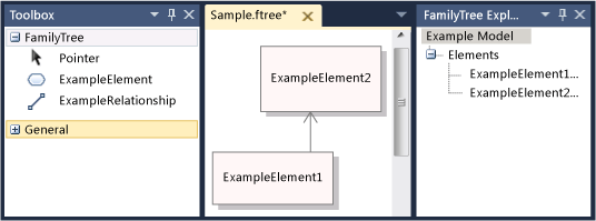
Your experimental Visual Studio will resemble the following example:
The Content of a Model
The content of a file that is an instance of a DSL is called a model. The model contains model elements and links between the elements. The DSL definition specifies what types of model elements and links can exist in the model. For example, in a DSL created from the Minimal Language template, there is one type of model element, and one type of link.
The DSL definition can specify how the model appears on a diagram. You can choose from a variety of styles of shapes and connectors. You can specify that some shapes appear inside other shapes.
You can view a model as a tree in the Explorer view while you are editing a model. As you add shapes to the diagram, the model elements also appear in the explorer. The explorer can be used even if there is no diagram.
If you cannot see the Explorer in the debugging instance of Visual Studio, on the View menu point to Other Windows, and then click <Your Language> Explorer.
The API of your DSL
Your DSL generates an API that allows you to read and update models that are instances of the DSL. One application of the API is to generate text files from a model. For more information, see Design-Time Code Generation by using T4 Text Templates.
In the Debugging solution, open the template files with extension ".tt". These samples demonstrate how you can generate text from models, and allow you to test the API of your DSL. One of the samples is written in Visual Basic, the other in Visual C#.
Under each template file is the file that it generates. Expand the template file in Solution Explorer, and open the generated file.
The template file contains a short segment of code that lists all the elements in the model.
The generated file contains the result.
When you change a model file, you will see corresponding changes in generated files after you regenerate the files.
To regenerate text files after you change the model file
In the experimental instance of Visual Studio, save the model file.
Make sure that the file name parameter in each .tt file refers to the model file that you are using for experiments. Save the .tt file.
Click Transform All Templates in the toolbar of Solution Explorer.
- or -
Right-click the templates that you want to regenerate and then click Run Custom Tool.
You can add any number of text template files to a project. Each template generates one result file.
Note
When you change the DSL definition, the sample text template code will not work, unless you update it.
For more information, see Generating Code from a Domain-Specific Language and Writing Code to Customize a Domain-Specific Language.
Customizing the DSL
When you want to modify the DSL definition, close the experimental instance and update the definition in the main Visual Studio instance.
Note
After you have modified the DSL definition, you might lose information in the test models that you have created by using earlier versions. For example, the debugging solution contains a file that is named Sample, which contains some shapes and connectors. After you start to develop your DSL definition, they will not be visible, and they will be lost when you save the file.
You can make a wide variety of extensions to your DSL. The following examples will give you an impression of the possibilities.
After each change, save the DSL definition, click Transform All Templates in Solution Explorer, and then press F5 to experiment with the changed DSL.
Rename the Types and Tools
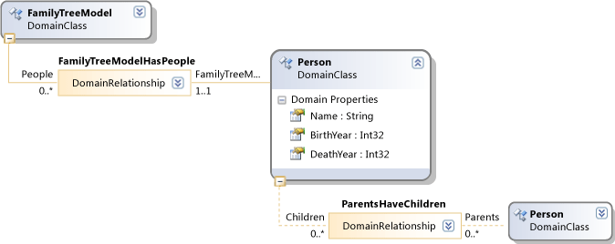
Rename the existing domain classes and relationships. For example, starting from a Dsl Definition created from the Minimal Language template, you could perform the following renaming operations, to make the DSL represent family trees.
To rename domain classes, relationships and tools
In the DslDefinition diagram, rename ExampleModel to FamilyTreeModel, ExampleElement to Person, Targets to Parents, and Sources to Children. You can click each label to change it.
Rename the element and connector tools.
Open the DSL Explorer window by clicking the tab under Solution Explorer. If you cannot see it, on the View menu point to Other Windows and then click DSL Explorer. DSL Explorer is visible only when the DSL Definition diagram is the active window.
Open the Properties window and position it so that you can see DSL Explorer and Properties at the same time.
In DSL Explorer, expand Editor, Toolbox Tabs, <your DSL>, and then Tools.
Click ExampleElement. This is the toolbox item that is used to create elements.
In the Properties window, change the Name property to Person.
Notice that the Caption property also changes.
In the same manner, change the name of the ExampleConnector tool to ParentLink. Alter the Caption property so that it is not a copy of the Name property. For example, enter Parent Link.
Rebuild the DSL.
Save the DSL Definition file.
Click Transform All Templates in the toolbar of Solution Explorer
Press F5. Wait until the experimental instance of Visual Studio appears.
In the Debugging solution in the experimental instance of Visual Studio, open a test model file. Drag elements onto it from the toolbox. Notice that the tool captions and the type names in DSL Explorer have changed.
Save the model file.
Open a .tt file and replace occurrences of the old type and property names with the new names.
Make sure that the file name that is specified in the .tt file specifies your test model.
Save the .tt file. Open the generated file to see the result of running the code in the .tt file. Verify that it is correct.
Add Domain Properties to Classes
Add properties to a domain class, for example to represent the years of birth and death of a Person.
To make the new properties visible on the diagram, you must add decorators to the shape that displays the model element. You must also map the properties to the decorators.
To add properties and display them
Add the properties.
In the DSL Definition diagram, right-click the Person domain class, point to Add, and then click Domain Property.
Type a list of new property names, such as Birth and Death. Press Enter after each one.
Add decorators that will display the properties in the shape.
Follow the gray line that extends from the Person domain class to the other side of the diagram. This is a diagram element map. It links the domain class to a shape class.
Right-click this shape class, point to Add, and then click Text Decorator.
Add two decorators with names such as BirthDecorator and DeathDecorator.
Select each new decorator, and in the Properties window, set the Position field. This determines where the domain property value will be displayed on the shape. For example, set InnerBottomLeft and InnerBottomRight.
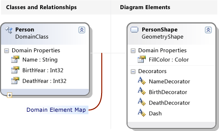
Map the decorators to the properties.
Open the DSL Details window. It is usually in a tab next to the Output window. If you cannot see it, on the View menu, point to Other Windows, and then click DSL Details.
On the DSL definition diagram, click the line that connects the Person domain class to the shape class.
In DSL Details, on the Decorator Maps tab, click the check box on an unmapped decorator. In Display Property, select the domain property to which you want it mapped. For example, map BirthDecorator to Birth.
Save the DSL, click Transform All Templates, and press F5.
In a sample model diagram, verify that you can now click the positions you chose and type values into them. In addition, when you select a Person shape, the Properties window displays the new properties Birth and Death.
In a .tt file, you can add code that obtains the properties of each person.
Define New Classes
You can add domain classes and relationships to a model. For example, you could create a new class to represent towns, and a new relationship to represent that a person lived in a town.
To make the different types distinct on a model diagram, you can map the domain classes to different kinds of shape, or to shapes with different geometry and colors.
To add and display a new domain class
Add a domain class and make it a child of the model root.
In the DSL Definition diagram, click the Embedding Relationship tool, click the root class FamilyTreeModel, and then click in an empty part of the diagram.
A new domain class appears, that is connected to the FamilyTreeModel with an embedding relationship.
Set its name, for example Town.
Note
Every domain class except the root of the model must be the target of at least one embedding relationship, or it must inherit from a class that is the target of an embedding. For this reason, it is frequently convenient to create a domain class by using the Embedding Relationship tool.
Add a domain property to the new class, for example Name.
Add a reference relationship between Person and Town.
Click the Reference Relationship tool, click Person and then click Town.
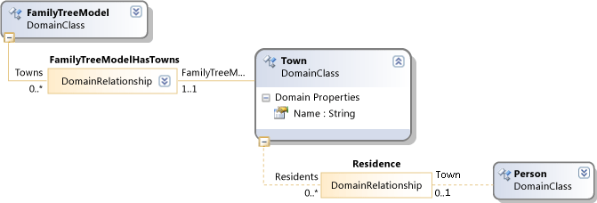
Note
Reference relationships represent cross-references from one part of the model tree to another.
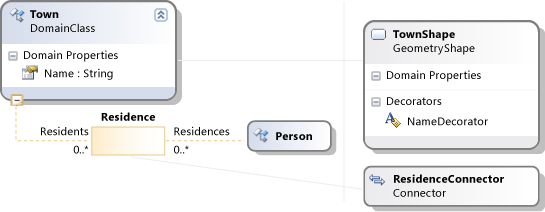
Add a shape to represent towns on the model diagrams.
Drag a Geometry Shape from the toolbox to the diagram and rename it, for example TownShape.
In the Properties window, set the Appearance fields of the new shape, such as Fill Color and Geometry.
Add a Decorator to display the name of the town, and rename it NameDecorator. Set its Position property.
Map the Town domain class to the TownShape.
Click the Diagram Element Map tool, then click the Town domain class, and then the TownShape shape class.
In the Decorator Maps tab of the DSL Details window with the map connector selected, check NameDecorator and set Display Property to Name.
Create a connector to display the relationship between Person and Towns.
Drag a Connector from the toolbox to the diagram. Rename it and set its appearance properties.
Use the Diagram Element Map tool to link the new connector to the relationship between Person and Town.
Create an element tool for making a new Town.
In DSL Explorer, expand Editor then Toolbox Tabs.
Right-click <your DSL> and then click Add New Element Tool.
Set the Name property of the new tool, and set its Class property to Town.
Set the Toolbox Icon property. Click [...] and in the File name field, select an icon file.
Create a connector tool for making a link between towns and people.
Right-click <your DSL> and then click Add New Connector Tool.
Set the Name property of the new tool.
In the ConnectionBuilder property, select the builder that contains the name of the Person-Town relationship.
Set the Toolbox Icon.
Save the DSL Definition, click Transform All Templates, and then press F5.
In the experimental instance of Visual Studio, open a test model file. Use the new tools to create towns and links between towns and persons. Notice that you can only create links between the correct types of element.
Create code that lists the town in which each person lives. Text templates are one of the places where you can run such code. For example, you could modify the existing Sample.tt file in the Debugging solution so that it contains the following code:
<#@ template inherits="Microsoft.VisualStudio.TextTemplating.VSHost.ModelingTextTransformation" debug="true" #>
<#@ output extension=".txt" #>
<#@ FamilyTree processor="FamilyTreeDirectiveProcessor" requires="fileName='Sample.ftree'" #>

<#
  foreach (Person person in this.FamilyTreeModel.People)
  {
#>
    <#= person.Name #><#if (person.Town != null) {#> of <#= person.Town.Name #> <#}#>

<#
      foreach (Person child in person.Children)
  {
#>
            <#= child.Name #>
<#
  }
  }
#>
When you save the *.tt file, it will create a subsidiary file that contains the list of people and their residences. For more information, see Generating Code from a Domain-Specific Language.
Validation and Commands
You could develop this DSL further by adding validation constraints. These constraints are methods that you can define, that make sure that the model is in a correct state. For example, you could define a constraint to make sure that the birth date of a child is later than that of its parents. The validation feature displays a warning if the DSL user tries to save a model that breaks any of the constraints. For more information, see Validation in a Domain-Specific Language.
You can also define menu commands that the user can invoke. Commands can modify the model. They can also interact with other models in Visual Studio and with external resources. For more information, see How to: Modify a Standard Menu Command.
Deploying the DSL
To allow other users to use the domain-specific language, you distribute a Visual Studio Extension (VSIX) file. This is created when you build the DSL solution.
Locate the .vsix file in the bin folder of your solution. Copy it to the computer on which you want to install it. On that computer, double-click the VSIX file. The DSL can be used in all instances of Visual Studio on that computer.
You can use the same procedure to install the DSL on your own computer so that you do not have to use the experimental instance of Visual Studio.
For more information, see Deploying Domain-Specific Language Solutions.
Removing old Experimental DSLs
If you have created experimental DSLs that you no longer want, you can remove them from your computer by resetting the Visual Studio Experimental instance.
This will remove from your computer all experimental DSLs and other experimental Visual Studio extensions. These are extensions that have been executed in debugging mode.
This procedure does not remove DSLs or other Visual Studio extensions that have been fully installed by executing the VSIX file.
To reset the Visual Studio Experimental instance
In the Windows Start menu, type reset the Visual Studio, and then run the Reset the Microsoft Visual Studio Experimental Instance command matching your version of Visual Studio.
Rebuild any experimental DSLs or other experimental Visual Studio extensions that you still want to use.
Related content
Feedback
Coming soon: Throughout 2024 we will be phasing out GitHub Issues as the feedback mechanism for content and replacing it with a new feedback system. For more information see: https://aka.ms/ContentUserFeedback.
Submit and view feedback for