USB Type-C manual interoperability test procedures
This article explains how to test the interoperability of USB Type-C enabled systems and Windows. It provides guidelines for device and system manufacturers to perform various functional and stress tests on systems and devices that expose a USB Type-C connector. It assumes that the reader is familiar with the official USB specification and xHCI interoperability test procedures, which can be downloaded from USB.ORG.
To run these tests by using the USB Type-C ConnEx board, see Test USB Type-C systems with USB Type-C ConnEx.
The test product can belong to one or more of the following categories:
- System: Desktops, laptops, tablets, servers, or phones with an exposed Type-C USB port. The system must be running a version of Windows 10, such as Windows 10 for desktop editions (Home, Pro, Enterprise, and Education), Windows 10 Mobile, or other versions.
- Dock: Any USB Type-C device that exposes more than one port.
- Device: Any USB device with a Type-C port that can be attached to a system or dock. This category includes traditional USB devices as well as devices that support the accessory and alternate modes as defined in the USB Type-C specification.
Official specifications and procedures
The USB Type-C interoperability test procedures are divided into two sections: functional testing (FT) and stress testing (ST). Each test section describes the test case and identifies the category that applies to the test. The product must be tested against the entire applicable category. Certain test cases contain links to relevant hints and tips for additional information. This document is focused on USB Type-C functionality and experience. A USB Type-C solution may contains other USB components such as a USB hub or USB controller. Detailed testing of USB hubs and controllers is covered in both the USB-IF's xHCI interoperability test procedures and the Windows Hardware Certification Kit.
- Device Enumeration: Confirms that core aspects of device enumeration are functional.
- System Boot: Confirms that the product does not inhibit normal system boot.
- System Power Transitions: Tests whether the system's power transitions and wake-up capability from lower power states are not affected by the product.
- Selective Suspend: Confirms the selective suspend transitions.
- Dock Identification: Confirm device descriptor in dock is properly implemented.
- Alternate Mode Negotiation: Confirm supported alternate modes.
- Charging and power delivery (PD): Confirm charging with USB Type-C.
- Role Swap: Confirm role swap.
The stress testing section describes procedures for stress and edge case scenarios, which test device stability over a period of time. Stress testing requires a custom device , the Microsoft USB Test Tool (MUTT) devices, for legacy USB validation (non USB Type-C). Additional testing and automation can be achieved with the upcoming USB Type-C test device.
- System Power Transitions: Tests product reliability after repetitive system power events.
- Transfer Events: Generates multiple transfer and connection events
- Plug and Play (PnP): Generates various PnP sequences.
- Device Topology: Tests a range of devices and topologies with the product.
FT Case 1: Device Enumeration
Applies to: System, dock, device
To confirm that device enumeration is functional:
Restart the test system and log on to Windows.
Open Device Manager on the test system. From Start, type devmgmt.msc in the Search text box.
Connect a device to a USB Type-C enabled system. Make sure the device is powered on or connected to an external power source, if necessary.
- System: Connect any USB Type-C device to the system.
- Device: Connect the device to a USB Type-C enabled system.
- Dock: Connect any USB 3.0 device and any USB Type-C device that supports alternate mode or is a USB Type-C accessory to the dock. Connect the dock to the system.
Confirm that the device node is added in Device Manager. For more information, see How to confirm device addition.
Confirm that the plugged in devices function without errors.
Disconnect the device (and dock if applicable) and observe changes in Device Manager. The dock and device should not appear in Device Manager. For more information, see How to confirm device removal.
Flip or reverse the orientation of USB Type-C cable and repeat steps 3 through 6.
FT Case 2: System Boot
Applies to: System, hub, device
To confirm that the product under test does not inhibit the normal system boot process**
Restart the test system and log on to Windows.
Connect the following USB devices to a system with an exposed USB Type-C port:
System: Connect these devices to an exposed USB Type-C port of the system by using a USB Type-C to USB Type-A adapter as shown in this image:
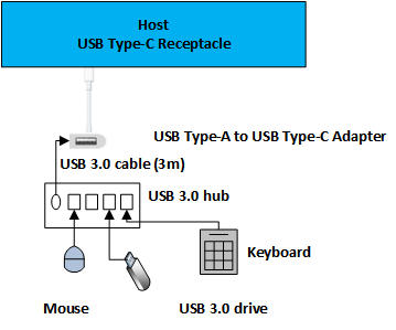
- USB hub
- USB keyboard
- USB 3.0 flash drive
Dock: Connect these devices to the ports exposed on the dock under test.
- USB hub
- USB keyboard
- USB 3.0 flash drive
Device: Connect your device to the exposed USB Type-C port of the system.
Open Device Manager on the test system. From Start, type devmgmt.msc in the Search text box.
Confirm that the device node is added in Device Manager. For more information, see How to confirm device addition.
Restart the system; make sure that the system shuts down and starts properly. Investigate system failures, if any.
For a system or dock testing, confirm the following:
- USB flash drive is recognized by UEFI / BIOS as bootable media and the system can be booted from it.
- USB keyboard is recognized by UEFI/BIOS and can be used to enter UEFI/BIOS.
After the system starts, confirm that devices appear in Device Manager, indicating that they were properly enumerated.
Validate the device functionality for all attached devices.
For a system repeat steps 3 through 8 by connecting a USB Type-C dock to the system with these devices connected to the dock.
- USB hub
- USB keyboard
- USB 3.0 flash drive
FT Case 3: System Power Transitions
Applies to: System, dock, device
To confirm that the system's power transitions and wake-up capability from lower power states are not affected by the product
- Restart the test system and log on to Windows.
- Attach a USB 3.0 hub to the exposed USB Type-C port on the system. For more information, see How to connect a device to a system.
- Connect a USB device to the hub.
- Open Device Manager on the test system.
- Confirm that devices are added in Device Manager. For more information, see How to confirm device addition.
- Send the system to a lower power state, such as Sleep or Hibernate, via the start menu or automation described below.
- Wake up the system from the lower power state. If the device supports remote wake, use the device to wake the system. For more information, see Troubleshooting system wake. Otherwise wake the system normally (by using the power button or the keyboard).
- Confirm that the device is still functional. For more information, see How to confirm device functionality.
Repeat this test for other available system power states: Sleep (S3), Hibernate (S4), and Hybrid Sleep.
Note
Use pwrtest.exe, included in the Windows Driver Kit (WDK), to simplify the transition to power states. For more information, see PwrTest.
FT Case 4: Selective Suspend
Applies to: Dock, device
To confirm that the device transitions to selective suspend
- Connect a USB bus analyzer between the test device and the system. For more information, see, Using an Analyzer to confirm Selective Suspend.
- Start a capture session.
- Allow device to enter selective suspend. Wait for 15 seconds while making sure that no transfers are active on the device. For example, if the test device is a flash drive, make sure no files are open; for a keyboard or mouse, leave the device in an idle state.
- Wake up the device from the selective suspend state by performing an action. For example, on the flash drive, open a file; for a keyboard, press a key, or move the mouse.
- In the analyzer, verify that the device entered the selective suspend state.
Additional information of selective suspend can be found from the following sources:
- Enabling selective suspend for HID
- Selective suspend for HID over USB devices
- Demystifying selective suspend
FT Case 5: Dock Identification
Applies to: Dock
- Restart the test system and log on to Windows.
- Connect the USB Type-C dock to the system.
- Ensure dock state is properly identified.
FT Case 6: Alternate Mode Negotiation
Applies to: System, dock, device
Confirm Alternate Mode negotiation for supported modes
Restart the test system and log on to Windows.
Open Device Manager on the test system. From Start, type devmgmt.msc in the Search text box.
Connect an alternate mode-enabled USB Type-C device to an alternate mode-enabled USB Type-C port on the system; make sure both the device and the system share at least one alternate mode in common and that the device is powered or connected to an external power source, if necessary.
Note
For Type-C dongles/adapters, ensure that an appropriate peripheral is powered on and connected to the non-Type-C end of the dongle/adapter.
Confirm that the alternate mode device is added in Device Manager. In some cases, the alternate mode device may show up as a Monitor device or another bus device. For more information, see How to confirm device addition.
Disconnect the device and observe changes in Device Manager. The hub and device should no longer appear in Device Manager. For more information, see How to confirm device removal.
Flip or reverse the orientation of the USB Type-C cable and repeat steps 2-5.
FT Case 7: Charging and power delivery (PD)
Applies to: System, dock, device that support USB power delivery protocol
Confirm charging with USB Type-C
Perform USB power deliver testing as defined by USB-IF.
Restart the test system and log on to Windows.
For a system, perform these steps:
- Connect two systems together with a USB Type-C cable. Confirm that only one system is receiving current.
- If systems contains more than one USB Type-C port, connect two USB Type-C ports on the same system with a USB Type-C cable. Confirm the system is not charging (itself).
- Connect the bundled USB Type-C charger (if bundled) to the USB Type-C port of the system. Confirm the system is charging.
- Repeat step 3c above with USB Type-C chargers from other sources.
- Connect USB Type-C device to the systems exposed USB Type-C port. Confirm the device is receiving current.
For a dock, perform these steps:
- Connect dock to USB Type-C enabled system with USB Type-C cable.
- Confirm the dock is charging the system connected.
For a device, perform these steps:
- Connect device the device to a USB Type-C enabled system. Confirm the device receives power from the system.
- (optional) Connect device the device to a USB Type-C enabled system. Confirm the device will charge the system.
FT Case 8: Role Swap
Applies to: System
Confirm role swap
- Restart the test system and log on to Windows.
- Connect two systems together with a USB Type-C cable.
- Confirm current roles of each system.
- Perform necessary steps to swap roles.
- Confirm current roles of each system have changed.
ST Case 1: System Power Transitions
Applies to: System, dock, device
- Restart the test system.
- Plug a USB SuperMUTT device to exposed USB Type-C port.
- Run the DF - Sleep with IO During test:
- Repeat step 3 with a USB Type-C test device.
ST Case 2: Transfer Events
Applies to: System, dock, device
- Restart the test system.
- Plug a USB SuperMUTT device to exposed USB Type-C port.
- Run the DF - Reboot Restart with IO Before and After test.
- Repeat step 3 with a USB Type-C test device.
ST Case 3: Plug and Play
Applies to: System, dock, device
- Restart the test system.
- Plug a USB SuperMUTT device to exposed USB Type-C port.
- Run the DF - Sleep and PNP with IO Before and After test.
- Repeat step 3 with a USB Type-C test device.
ST Case 4: Device Topology
Applies to: System, dock, device
Restart the test system.
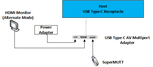
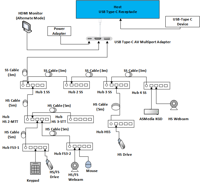
By using a USB Type-C A/V adapter, connect all ports of the A/V adapter so all functionality can be used as shown in this image:
If the system under test has additional USB Type-C ports, repeat step 2.
Run the DF - Sleep with IO During test.
Note
During the test, validate there is no glitching from devices connected via the USB Type-C A/V dongle such as video distortion or audio drop off.
Functional system interoperability test plan
Expected duration: 20 minutes
The goal of this plan is to determine whether the system can work with different types of peripherals and chargers. This test plan focuses on testing from sources other than the OEM for the system.
Systems: Windows 10Windows 10 system (PC, tablet or phone) with exposed USB Type-C port.
Peripherals
- USB Type-A to USB Type-C adapter - USB 3.0 hub - USB mouse - USB 3.0 flash drive
- USB Type-C storage drive
- USB Type-C video (dongle is acceptable)
Power supply: USB Type-C charger
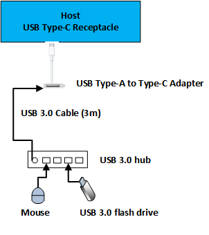
Perform FT Case 1: Device Enumeration for USB Type-C dongle. Verify that each device enumerates and functions as expected. This image shows the recommended topology for testing the USB Type A dongle.
Perform FT Case 6: Alternate mode negotiation for the remaining peripherals in the list. Verify that each device enumerates and functions as expected.
Perform a reduced version of FT Case 7: Charging and power delivery (PD) with the USB Type-C charger. Skip the sections requiring two machines and only validate that the system is able to charge (accept power) with a third-party power adapter.
Usability system interoperability test plan
Expected duration: 60 minutes
The goal of this plan is to determine whether this system can perform the most common user scenarios with USB Type-C peripherals. This test plan makes an assumption of successful completion of tests outlined in the Functional system interoperability test plan. The usability test plan focuses on common user, system, and device scenarios.
Systems: Windows 10Windows 10 system (PC, tablet or phone) with exposed USB Type-C port.
Peripherals
- USB Type-A to USB Type-C adapter - USB 3.0 hub - USB mouse - USB 3.0 flash drive
- USB Type-C storage drive
- USB Type-C video (dongle is acceptable)
- USB Type-C A/V dongle (includes both video, USB, and possibly audio as a single adapter)
Power supply: Two USB Type-C chargers from different suppliers.
Perform FT Case 3: System Power Transitions for each peripheral in the list with USB to Type-C dongle. Verify that each device enumerates and functions as expected before and after the system power state changes.
- Configure The USB Type-A to USB Type-C adapter as shown in this image:
Configure the USB Type-C A/V dongle as shown in this image.
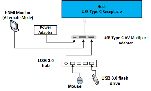
Perform FT Case 2: System Boot with only the USB Type-C A/V dongle configured as shown in the preceding image and validate these scenarios:
- System will boot with all devices connected and video will display in monitor connected through USB Type-C A/V dongle.
- System will boot from USB disk attached through USB Type-C A/V dongle.
Full interoperability test plan
Expected duration: 180+ minutes
The full interoperability test plan covers a larger set of user scenarios. Run these tests when the system of device is preparing for USB-IF certification.
Systems
- Windows 10Windows 10 system (PC, tablet or phone) with exposed USB Type-C port.
- Additional Windows 10Windows 10 system (PC, tablet or phone) with exposed USB Type-C port. system (PC, tablet or phone) with exposed USB Type-C port. We recommend a system from another product line or OEM.
Peripherals
- USB Type-A to Type-C adapterUSB Type-A to USB Type-C adapter - USB 3.0 hub - USB mouse - USB 3.0 flash drive
- USB Type-C storage drive - USB Type-C video (dongle is acceptable) - USB Type-C A/V dongle (includes video, audio, and USB as a single unit)
Power supply: Two USB Type-C chargers from different suppliers.
Perform all function stress test cases. Suggested configuration for the USB Type-C A/V is shown in this image:
How to confirm device addition
- Identify the USB host controller to which your device is connected.
- Make sure that the new device appears under the correct node in Device Manager.
- For USB 3.0 hubs connected to a USB 3.0 port, expect to see two devices: one downstream of the USB 3.0 and another downstream of the full speed hub.
How to confirm device removal
- Identify your device in Device Manager.
- Perform the test step to remove the device from the system.
- Confirm that the device is no longer present in Device Manager.
- For a USB 3.0 hub, check that both devices (SuperSpeed and companion hubs) are removed. Failure to remove a device in this case may be a device failure and should be investigated by all components involved to triage the appropriate root cause.
How to confirm device functionality
- If the device is a USB hub, make sure that the devices that are downstream of the hub are functional. Verify that other devices can be connected to available ports on the hub.
- If the device is an HID device, test its functionality. Make sure that a USB keyboard types, a USB mouse moves the cursor, and a gaming device is functional in the game controller's control panel.
- A USB audio device must play and/or record sound.
- A storage device must be accessible and should be able to copy a file 200MB or more in size.
- If the device has multiple functions, such as scan & print, make sure to test both the scan and print functionality.
- If the device is a USB Type-C, confirm applicable USB and alternate modes are functional.
How to connect a device to a System
- Make sure that USB 3.x devices use a USB 3.x cable appropriate to the test device.
- If the device is not recognized by the system, attempt to connect the device with a different cable of the same type to check for bad cables or connectors.
Troubleshooting system wake
To troubleshoot a device that is not able to wake up the system:
- Confirm that the device is wake-up capable.
- Confirm that the host controller, to which the device is attached, is set up to wake the system.
Troubleshooting missing power states
If your test system is unable to reach a Sleep or Hibernate state, make sure that all devices in the system have the latest device drivers installed. One of the most common causes is an unsupported video card in the system.
Using ETW to log issues
To enable ETW for USB 2.0 ports, see ETW in the Windows 7 USB core stack.
To enable USB 3.0 logging, perform the following commands instead (or see How to capture a USB event trace with Logman):
logman start usbtrace -ets -o usbtrace.etl -nb 128 640 -bs 128
logman update usbtrace -ets -p Microsoft-Windows-USB-UCX Default
logman update usbtrace -ets -p Microsoft-Windows-USB-USBHUB3 Default
After these are logs are captured, perform the test scenario.
Stop the trace by using this command:
logman stop usbtrace -ets
Using an Analyzer to confirm Selective Suspend
To analyze USB 2.0 and 3.0 traffic, you will need a USB Analyzer device such as the LeCroy Voyager M3i, Advisor T3, or a TotalPhase Beagle 5000. These analyzers are capable of capturing and displaying link state information necessary to confirm selective suspend functionality.
For example, after capturing traffic with a TotalPhase analyzer, you will see an event similar to the following in the output:

When a test requires the device to go to a suspended state, you should be able to correlate the <Suspend> event above with the time at which you expected the device to go to the suspend state.
Using an Analyzer to confirm LPM U1 and U2 transitions
An analyzer trace should explicitly show every link state transition: statements appear as "Rx U0 -> U2" in the events. For example, by using LeCroy software, in the Report tab, select the USB3 Link State Timing View. This option shows the link state on a time axis. Note that at times the analyzer might not show the U1 to U2 transition correctly. You might see the link state going into U1 but recovering back from U2.
Disabling Selective Suspend in Device Manager
In order to disable selective suspend on a USB device in Device Manager, first find the device node in the device tree. In this example, disable selective suspend on the hub shown below:

Right-click the device and select Properties. Then select the Power Management tab.
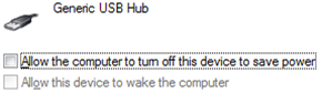
To disable selective suspend, make sure the Allow the computer to turn off this device to save power checkbox is clear.
Flipping or reversing the USB Type-C cable
The USB Type-C cable is intended to maintain user functionality regardless of cable orientation. Flipping or reversing the cable is achieved by removing cable, rotating it 180 degrees and reinserting the cable.
Reporting test results
Provide these details:
- The list of tests (in order) that were performed before the failed test.
- The list must specify the tests that have failed or passed.
- Systems, devices, docks, or hubs that were used for the tests. Include make, model, and Web site so that we can get additional information, if needed.
Feedback
Coming soon: Throughout 2024 we will be phasing out GitHub Issues as the feedback mechanism for content and replacing it with a new feedback system. For more information see: https://aka.ms/ContentUserFeedback.
Submit and view feedback for