GDIINFO structure (winddi.h)
The GDIINFO structure describes the graphics capabilities of a given device.
Syntax
typedef struct _GDIINFO {
  ULONG     ulVersion;
  ULONG     ulTechnology;
  ULONG     ulHorzSize;
  ULONG     ulVertSize;
  ULONG     ulHorzRes;
  ULONG     ulVertRes;
  ULONG     cBitsPixel;
  ULONG     cPlanes;
  ULONG     ulNumColors;
  ULONG     flRaster;
  ULONG     ulLogPixelsX;
  ULONG     ulLogPixelsY;
  ULONG     flTextCaps;
  ULONG     ulDACRed;
  ULONG     ulDACGreen;
  ULONG     ulDACBlue;
  ULONG     ulAspectX;
  ULONG     ulAspectY;
  ULONG     ulAspectXY;
  LONG      xStyleStep;
  LONG      yStyleStep;
  LONG      denStyleStep;
  POINTL    ptlPhysOffset;
  SIZEL     szlPhysSize;
  ULONG     ulNumPalReg;
  COLORINFO ciDevice;
  ULONG     ulDevicePelsDPI;
  ULONG     ulPrimaryOrder;
  ULONG     ulHTPatternSize;
  ULONG     ulHTOutputFormat;
  ULONG     flHTFlags;
  ULONG     ulVRefresh;
  ULONG     ulBltAlignment;
  ULONG     ulPanningHorzRes;
  ULONG     ulPanningVertRes;
  ULONG     xPanningAlignment;
  ULONG     yPanningAlignment;
  ULONG     cxHTPat;
  ULONG     cyHTPat;
  LPBYTE    pHTPatA;
  LPBYTE    pHTPatB;
  LPBYTE    pHTPatC;
  ULONG     flShadeBlend;
  ULONG     ulPhysicalPixelCharacteristics;
  ULONG     ulPhysicalPixelGamma;
} GDIINFO, *PGDIINFO;
Members
ulVersion
Specifies the driver version number. The byte ordering of ulVersion has the following form.
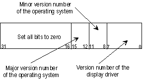
The high-order 16 bits must be set to zero. Bits 8 through 15 specify the version number of the Microsoft operating system for which the driver is designed. The high-order 4 bits of this range specify the major number of the version, the low-order 4 bits contain the minor number of the version. The low-order 8 bits of ulVersion specify the version number of the display driver; this value should be incremented for each release of the display driver binary file.
The Display program in Control Panel indicates the version number contained in ulVersion, along with other driver-specific information.
ulTechnology
Specifies the device technology. This member can be one of the values listed in the following table.
| Value | Meaning |
|---|---|
| DT_CHARSTREAM | Device fonts only |
| DT_PLOTTER | Vector plotter |
| DT_RASCAMERA | Raster camera |
| DT_RASDISPLAY | Raster display |
| DT_RASPRINTER | Raster printer |
ulHorzSize
Specifies the width of the physical surface. A positive value indicates that the width is in units of millimeters, while a negative value denotes that the width is in units of micrometers.
ulVertSize
Specifies the height of the physical surface. A positive value indicates that the height is in units of millimeters, while a negative value denotes that the height is in units of micrometers.
ulHorzRes
Specifies the width in pixels of the physical surface (display devices), or of the printable surface (printers).
See also ulDesktopHorzRes.
ulVertRes
Specifies the height in pixels of the physical surface (display devices), or of the printable surface (printers).
cBitsPixel
Specifies the number of adjacent bits in each color plane. The total number of bits per pixel is the product of cBitsPixel and cPlanes.
cPlanes
Specifies the number of color planes.
ulNumColors
For palettized devices, ulNumColors specifies the number of entries in the default color palette. For nonpalettized devices (which do not include printers), ulNumColors is set to -1.
flRaster
Is reserved and must be left set to zero.
ulLogPixelsX
Specifies the width resolution of the device in logical pixels per inch.
For printers, this member should be set to the printer's resolution in dpi.
For displays, this member must be set to 96.
ulLogPixelsY
Specifies the height resolution of the device in logical pixels per inch.
For printers, this member should be set to the printer's resolution in dpi.
For displays, this member must be set to 96.
flTextCaps
Specifies a flag describing Windows 3.1 text capabilities. If the driver TC_SCROLLBLT flag is in this member, it indicates that the console should perform text scrolling by redrawing the entire screen, using the driver-supplied DrvTextOut function rather than the DrvBitBlt or DrvCopyBits functions. The driver should set this flag if screen-to-screen bit-block transfers are slow. If this flag is not set, the driver is implicitly requesting that the console perform text scrolls through DrvBitBlt/DrvCopyBits.
ulDACRed
ulDACGreen
ulDACBlue
Specifies the display number of DAC bits for the specified color.
ulAspectX
Specifies the relative width of a device pixel, in the range of one to 1000.
ulAspectY
Specifies the relative height of a device pixel, in the range of one to 1000.
ulAspectXY
Specifies the square root of the sum of the squares of ulAspectX and ulAspectY.
xStyleStep
Specifies the numerator of style advance for x-major lines, dx. For additional information, refer to the following Remarks section and Styled Cosmetic Lines.
yStyleStep
Specifies the numerator of style advance for y-major lines, dy. For additional information, refer to the following Remarks section and Styled Cosmetic Lines.
denStyleStep
Specifies the denominator of style advance, D. For additional information, refer to the following Remarks section and Styled Cosmetic Lines.
ptlPhysOffset
Specifies a POINTL structure that contains the size, in pixels, of the unwritable margin of a surface.
szlPhysSize
Specifies a SIZEL structure that contains the size, in pixels, of the entire surface, including unwritable margins. A SIZEL structure is identical to a SIZE structure.
ulNumPalReg
Specifies the number of palette registers for an indexed device.
ciDevice
Is a COLORINFO structure that defines the device's colors in CIE coordinate space.
ulDevicePelsDPI
For printers, specifies the number of pixels (or dots, or nozzles) per inch if the pixels are laid out side by side without overlapping or space between. For example, if the size of a pixel is 0.001 inch, this value is equal to one-divided-by 0.001. If the member is zero, GDI halftoning calculates this number based on the assumption that all pixels are connected with no overlapping.
Because the physical dot size for most printers is larger than the measured dot size, GDI uses this value to approximate how many physical dots can be placed, based on the cell size (pattern size). A log regression is then performed to determine what is most linear; that is, where the dots should be placed for the best coverage to optimize the overlapped device pixels coverage (dot gain).
For displays, this member should be set to zero.
ulPrimaryOrder
Specifies the bit order of the device's primary colors or plane numbers for the halftone output. This member can be one of the values listed in the following table.
| Flag | Meaning |
|---|---|
| PRIMARY_ORDER_ABC | Device output order is RGB or CMY. Red or cyan is in the least significant bits; blue or yellow is in the most significant bits. |
| PRIMARY_ORDER_ACB | Device output order is RBG or CYM. Red or cyan is in the least significant bits; green or magenta is in the most significant bits. |
| PRIMARY_ORDER_BAC | Device output order is GRB or MCY. Green or magenta is in the least significant bits; blue or yellow is in the most significant bits. |
| PRIMARY_ORDER_BCA | Device output order is GBR or MYC. Green or magenta is in the least significant bits; red or cyan is in the most significant bits. |
| PRIMARY_ORDER_CBA | Device output order is BGR or YMC. Blue or yellow is in the least significant bits; red or cyan is in the most significant bits. |
| PRIMARY_ORDER_CAB | Device output order is BRG or YCM. Blue or yellow is in the least significant bits; green or magenta is in the most significant bits. |
ulHTPatternSize
Specifies the size of the halftone pattern. The values ending with AxBM are variations of the AxB patterns. In other words, SIZEAxB and SIZE_AxB_M differ by which pixels are lit in an A x B pattern. This member can be one of the following values:
- HT_PATSIZE_2x2
- HT_PATSIZE_2x2_M
- HT_PATSIZE_4x4
- HT_PATSIZE_4x4_M
- HT_PATSIZE_6x6
- HT_PATSIZE_6x6_M
- HT_PATSIZE_8x8
- HT_PATSIZE_8x8_M
- HT_PATSIZE_10x10
- HT_PATSIZE_10x10_M
- HT_PATSIZE_12x12
- HT_PATSIZE_12x12_M
- HT_PATSIZE_14x14
- HT_PATSIZE_14x14_M
- HT_PATSIZE_16x16
- HT_PATSIZE_16x16_M
- HT_PATSIZE_SUPERCELL
- HT_PATSIZE_SUPERCELL_M
- HT_PATSIZE_USER
- HT_PATSIZE_MAX_INDEX
- HT_PATSIZE_DEFAULT
ulHTOutputFormat
Specifies the preferred output format for halftone. HT_FORMAT_4BPP uses only 8 full intensity colors while HT_FORMATP_IRGB uses all the 16 colors including the half-intensity colors. It is assumed that a 5 x 5 x 5 format (5 bits per color) is used for HT_FORMAT_16BPP. This member can be one of the following values:
- HT_FORMAT_1BPP
- HT_FORMAT_4BPP
- HT_FORMAT_4BPP_IRGB
- HT_FORMAT_8BPP
- HT_FORMAT_16BPP
- HT_FORMAT_24BPP
- HT_FORMAT_32BPP
flHTFlags
Specifies a combination of flags describing the device. These flags are needed for halftoning. This member can be a combination of the following values:
| Flag | Meaning |
|---|---|
| HT_FLAG_8BPP_CMY332_MASK | Flag used to clear the upper eight bits of flHTFlags (bits 24 to 31). The MAKE_CMY332_MASK macro can then be used to set these bits with 8-bit-per-pixel CMY mode ink level information. See Using GDI 8-Bit-Per-Pixel CMY Mask Modes for more information. |
| HT_FLAG_ADDITIVE_PRIMS | Device primaries are additive. |
| HT_FLAG_DO_DEVCLR_XFORM | Requests GDI to perform generic color correction. |
| HT_FLAG_HAS_BLACK_DYE | Device has separate black dye. |
|
Paper in device absorbs more than normal amount of ink, so GDI should render less ink to paper. These flags indicate the relative amount of ink absorption, with HT_FLAG_HIGHER_INK_ABSORPTION denoting more absorption than HT_FLAG_HIGH_INK_ABSORPTION, but less than HT_FLAG_HIGHEST_INK_ABSORPTION. |
|
Flags used to define HT_FLAG_HIGH/HIGHER/HIGHEST_INK_ABSORPTION and HT_FLAG_LOW/LOWER/LOWEST_INK_ABSORPTION. |
| HT_FLAG_INK_HIGH_ABSORPTION | Flag used to define HT_FLAG_HIGH/HIGHER/HIGHEST_INK_ABSORPTION. |
| HT_FLAG_INVERT_8BPP_BITMASK_IDX | GDI halftone should render 8-bit-per-pixel ask mode surface bitmap using a CMY_INVERTED mode palette. See Using GDI 8-Bit-Per-Pixel CMY Mask Modes for CMY_INVERTED mode palette description and requirements. |
|
Paper in device absorbs less than normal amount of ink, so GDI should render more ink to paper. These flags indicate the relative amount of ink absorption, with HT_FLAG_LOWER_INK_ABSORPTION denoting less absorption than HT_FLAG_LOW_INK_ABSORPTION, but more than HT_FLAG_LOWEST_INK_ABSORPTION. |
| HT_FLAG_NORMAL_INK_ABSORPTION | Paper in device absorbs normal amount of ink. |
| HT_FLAG_OUTPUT_CMY | Device uses CMY primaries rather than RGB primaries. This flag value applies only to 1 bpp and 4 bpp destination surfaces. |
| HT_FLAG_PRINT_DRAFT_MODE | Disables GDI's antialiasing code. |
| HT_FLAG_SQUARE_DEVICE_PEL | Device pixel is square rather than round (displays only -- printers require rounded pixels). |
| HT_FLAG_USE_8BPP_BITMASK | Device uses monochrome printing. |
ulVRefresh
The video refresh rate for the current display mode. This is the value returned by the miniport driver for the refresh rate for the current mode.
The Display program in Control Panel displays the refresh rate contained in the ulVRefresh member.
ulBltAlignment
This member indicates the preferred x-alignment for bit block transfers to the device. A value of zero indicates that bit block transfers are accelerated; any other nonnegative number indicates that bit block transfers are not accelerated, and gives the preferred horizontal alignment as a pixel multiple.
This value is used by the system to determine the default alignment for window positions and is also used to set the initial full-drag default during setup. A value of zero indicates that full-drag should be on by default; any value other than zero indicates that full-drag should be off by default.
ulPanningHorzRes
ulPanningVertRes
Should be ignored by the driver and remain zero-initialized.
xPanningAlignment
yPanningAlignment
Should be ignored by the driver and remain zero-initialized.
cxHTPat
cyHTPat
Specify the width and height, respectively, in pixels, of the user-supplied halftone dither pattern. The value of cxHTPat must be in the range HT_USERPAT_CX_MIN to HT_USERPAT_CX_MAX, inclusive. The value of cyHTPat must be in the range HT_USERPAT_CY_MIN to HT_USERPAT_CY_MAX, inclusive. These constants are defined in winddi.h. See the following Remarks section for more information.
pHTPatA
pHTPatB
pHTPatC
Point to the user-defined halftone dither patterns for primary colors A, B, and C, respectively, as defined by the PRIMARY_ORDER_XXX value in the ulPrimaryOrder member. Each dither pattern must be a valid two-dimensional byte array of size cxHTPat by cyHTPat. See the following Remarks section for more information.
flShadeBlend
Specifies a set of flags that indicate the shading and blending capabilities of the device. Display drivers should ignore this member and should leave it set to zero. For printer drivers, the value that the driver places in this member is the value that GDI reports when an application calls GetDeviceCaps(hdc, SHADEBLENDCAPS). The GetDeviceCaps function is described in the Microsoft Window SDK documentation.
ulPhysicalPixelCharacteristics
Specifies the way that color fragments are configured to form pixels on the display device. The color fragments on the display device can be arranged in RGB order, or in BGR order, completely independent of the RGB ordering in the frame buffer. The color fragments can be configured in horizontal stripes in which all of the fragments in one row are the same color. Alternatively, the color fragments can be configured in vertical stripes, in which all fragments in one column are the same color. Vertical striping is preferred, since it effectively provides three separate fragments in a row for each pixel, thereby giving greater horizontal subpixel resolution.
The ulPhysicalPixelCharacteristics member must be set to one of the values shown in the following table:
| Value | Meaning |
|---|---|
| PPC_DEFAULT | Display device physical pixel information is unknown. |
| PPC_BGR_ORDER_HORIZONTAL_STRIPES | Physical color fragments on the display device are arranged, from top to bottom, in rows of blue, green, and red color fragments. |
| PPC_BGR_ORDER_VERTICAL_STRIPES | Physical color fragments on the display device are arranged, from left to right, in columns of blue, green, and red color fragments. |
| PPC_RGB_ORDER_HORIZONTAL_STRIPES | Physical color fragments on the display device are arranged, from top to bottom, in rows of red, green, and blue color fragments. |
| PPC_RGB_ORDER_VERTICAL_STRIPES | Physical color fragments on the display device are arranged, from left to right, in columns of red, green, and blue color fragments. |
| PPC_UNDEFINED |
Display device physical pixel information is known but cannot be expressed as one of the given enumerations. The enumerations are currently applicable to an LCD-based monitor. The driver should set ulPhysicalPixelCharacteristics to PPC_UNDEFINED when either of the following conditions is met. (This list is not comprehensive, but covers the most common conditions.)
|
ulPhysicalPixelGamma
Specifies the gamma of the display device. This member should be set to either the gamma of the physical pixel, scaled by a factor of 1000, or to one of the following values. For example, a gamma value of 2.2 would be represented as 2200.
| Value | Meaning |
|---|---|
| PPG_DEFAULT | The driver has no knowledge of the gamma for the device. |
| PPG_SRGB | The device uses an sRGB gamma. |
Remarks
GDI zero-initializes this structure before calling the driver-supplied DrvEnablePDEV function.
The xStyleStep, yStyleStep, and denStyleStep members define how a cosmetic line style should advance as it draws each pixel of a cosmetic line. The amount advanced along the style for each pixel is defined as a fraction that depends on whether the line is x-styled or y-styled. If the line is x-styled, the style advances by the fractional amount dx/D for each pixel moved in the x direction. Otherwise the style advances by dy/D for each pixel moved in the y direction.
The dots in the predefined line style PS_DOT are each one unit long. If the driver defines xStyleStep as one and denStyleStep as 5, then a dotted horizontal line consists of 5-pixels-on followed by 5-pixels-off, repeated.
Each of these three numbers must be less than 65536, even though the caps members are LONG values. These style steps are defined by the driver to ensure that the dots and dashes in a line are a pleasing size on the output device. The horizontal and vertical steps can be different to correct for nontrivial aspect ratios. For example, on an EGA display, whose pixels are 33 percent higher than they are wide, you can set:
pdevcaps->xStyleStep   =  3;    // For an EGA
pdevcaps->yStyleStep   =  4;
pdevcaps->denStyleStep = 12;
In this case, horizontal dotted lines are 4-pixels-on, 4-pixels-off, because the style advances by 3/12 or 1/4 for each pixel. Vertical dotted lines are 3-pixels-on/3-pixels-off.
Styled lines look better if both the x and y style steps divide evenly into the style denominator, as they do in the preceding example. This gives dashes and dots that are always the same length.
GDI needs this information so that its bitmap functions can emulate exactly what the device does on its own surface. Applications can access this information to determine exactly which pixels will be turned on for styled lines. Refer also to Styled Cosmetic Lines.
The halftone-related members, cxHTPat, cyHTPat, pHTPatA, pHTPatB, and pHTPatC, can be used in an OEM Unidrv rendering plug-in to define a custom halftone pattern consisting of either one or three colors. These members are checked only if the ulHTPatternSize member is set to HT_PATSIZE_USER. In this case an OEM can use these members to define a custom halftone pattern, based on data stored in a resource file or generated by an OEM customization module. The cxHTPat and cyHTPat members define the size of each of the three two-dimensional halftone pattern arrays. The pHTPatA, pHTPatB, and pHTPatC members point to the respective pattern arrays for each color. If only one pattern array is used, pHTPatA, pHTPatB, and pHTPatC point to it.
Each byte threshold at a particular location in a halftone dither pattern determines whether the pixel at the corresponding output plane location will be on or off. A zero threshold value at a particular location in the pattern array indicates that the corresponding pixel location is ignored (is black). Threshold values from 1 to 255 provide the dither pattern with 255 levels of gray; if the pixel value in the output plane is greater than or equal to the threshold value for that location, the pixel is turned on. A pixel value less than its corresponding threshold value causes its pixel to be turned off in the output plane. See Customized Halftoning in Customizing Microsoft's Printer Drivers for more information.
Requirements
| Requirement | Value |
|---|---|
| Header | winddi.h (include Winddi.h) |
See also
Feedback
Coming soon: Throughout 2024 we will be phasing out GitHub Issues as the feedback mechanism for content and replacing it with a new feedback system. For more information see: https://aka.ms/ContentUserFeedback.
Submit and view feedback for