How to: Create a basic Lambert shader
Applies to: ![]() Visual Studio
Visual Studio ![]() Visual Studio for Mac
Visual Studio for Mac
Note
This article applies to Visual Studio 2017. If you're looking for the latest Visual Studio documentation, see Visual Studio documentation. We recommend upgrading to the latest version of Visual Studio. Download it here
This article demonstrates how to use the Shader Designer and the Directed Graph Shader Language (DGSL) to create a lighting shader that implements the classic Lambert lighting model.
The Lambert lighting model
The Lambert lighting model incorporates ambient and directional lighting to shade objects in a 3D scene. The ambient components provide a base level of illumination in the 3D scene. The directional components provide additional illumination from directional (far-away) light sources. Ambient illumination affects all surfaces in the scene equally, regardless of their orientation. For a given surface, it's a product of the ambient color of the surface and the color and intensity of ambient lighting in the scene. Directional lighting affects every surface in the scene differently, based on the orientation of the surface with respect to the direction of the light source. It's a product of the diffuse color and orientation of the surface, and the color, intensity, and direction of the light sources. Surfaces that face directly toward the light source receive the maximum contribution and surfaces that face directly away receive no contribution. Under the Lambert lighting model, the ambient component and one or more directional components are combined to determine the total diffuse color contribution for each point on the object.
Before you begin, make sure that the Properties window and the Toolbox are displayed.
Create a DGSL shader with which to work. For information about how to add a DGSL shader to your project, see the Getting Started section in Shader Designer.
Disconnect the Point Color node from the Final Color node. Choose the RGB terminal of the Point Color node, and then choose Break Links. Leave the Alpha terminal connected.
Add a Lambert node to the graph. In the Toolbox, under Utility, select Lambert and move it to the design surface. The lambert node computes the total diffuse color contribution of the pixel, based on ambient and diffuse lighting parameters.
Connect the Point Color node to the Lambert node. In Select mode, move the RGB terminal of the Point Color node to the Diffuse Color terminal of the Lambert node. This connection provides the lambert node with the interpolated diffuse color of the pixel.
Connect the computed color value to the final color. Move the Output terminal of the Lambert node to the RGB terminal of the Final Color node.
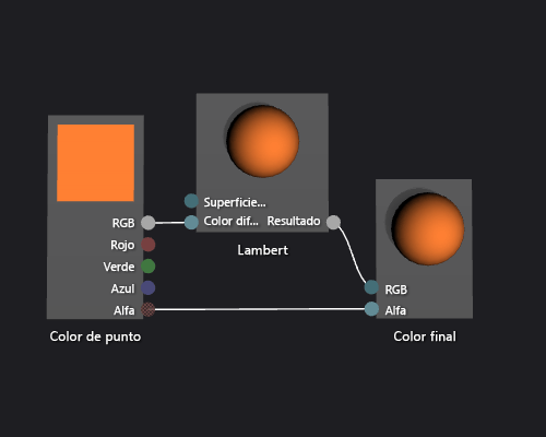
The following illustration shows the completed shader graph and a preview of the shader applied to a teapot model.
Note
To better demonstrate the effect of the shader in this illustration, an orange color has been specified by using the MaterialDiffuse parameter of the shader. A game or app can use this parameter to supply a unique color value for each object. For information about material parameters, see the Previewing Shaders section in Shader Designer.
Certain shapes might provide better previews for some shaders. For more information about how to preview shaders in the Shader Designer, see the Previewing Shaders section in Shader Designer.
The following illustration shows the shader that's described in this document applied to a 3D model.

For more information about how to apply a shader to a 3D model, see How to: Apply a Shader to a 3D Model.