ExpressRoute Microsoft 피어링을 통해 사이트 간 VPN 구성
이 문서를 사용하면 ExpressRoute 프라이빗 연결을 통해 온-프레미스 네트워크와 Azure VNet(가상 네트워크) 간에 암호화된 보안 연결을 구성할 수 있습니다. Microsoft 피어링을 사용하여 선택한 온-프레미스 네트워크와 Azure VNet 간에 사이트 간 IPsec/IKE VPN 터널을 설정할 수 있습니다. ExpressRoute를 통해 보안 터널을 구성하면 기밀성, 재생 방지, 신뢰성 및 무결성이 보장된 데이터 교환이 가능합니다.
참고
Microsoft 피어링을 통해 사이트 간 VPN을 설정하면 VPN Gateway 및 VPN 송신에 대한 요금이 청구됩니다. 자세한 내용은 VPN Gateway 가격 책정을 참조하세요.
이 문서의 단계 및 예제에서는 Azure PowerShell Az 모듈을 사용합니다. 컴퓨터에 Az 모듈을 로컬로 설치하려면 Azure PowerShell 설치를 참조하세요. 새 Az 모듈에 대한 자세한 내용은 새 Azure PowerShell Az 모듈 소개를 참조하세요. PowerShell cmdlet은 자주 업데이트됩니다. 최신 버전을 실행하지 않는 경우 지침에 지정된 값이 실패할 수 있습니다. 시스템에 설치된 PowerShell 버전을 찾으려면 Get-Module -ListAvailable Az cmdlet을 사용합니다.
아키텍처
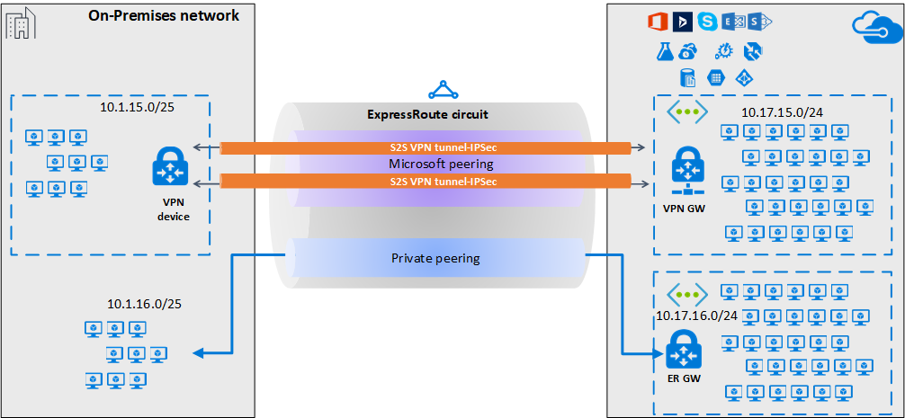
고가용성 및 중복성을 위해 ExpressRoute 회로의 두 MSEE-PE 쌍을 통해 여러 터널을 구성할 수 있으며 터널 간에 부하 분산을 사용할 수 있습니다.
VPN Gateway를 사용하거나 Azure Marketplace를 통해 사용할 수 있는 적절한 NVA(네트워크 가상 어플라이언스)를 사용하여 Microsoft 피어링을 통한 VPN 터널을 종료할 수 있습니다. 기본 Microsoft 피어링에 경로 교환을 노출하지 않고 암호화된 터널을 통해 경로를 정적으로 또는 동적으로 교환할 수 있습니다. 이 문서의 예제에서는 BGP(Microsoft 피어링을 만드는 데 사용되는 BGP 세션과 다름)를 사용하여 암호화된 터널을 통해 동적으로 접두사를 교환합니다.
Important
온-프레미스 측의 경우 일반적으로 Microsoft 피어링은 DMZ에서 종료되고 프라이빗 피어링은 핵심 네트워크 영역에서 종료됩니다. 두 영역은 방화벽을 사용하여 분리됩니다. ExpressRoute를 통해 보안 터널링을 사용하기 위해 배타적으로 Microsoft 피어링을 구성하는 경우 Microsoft 피어링을 통해 보급되는 주요 공용 IP만을 필터링해야 합니다.
워크플로
- ExpressRoute 회로에 Microsoft 피어링을 구성합니다.
- Microsoft 피어링을 통해 온-프레미스 네트워크에 선택한 Azure 지역 공용 접두사를 보급합니다.
- VPN Gateway를 구성하고 IPsec 터널을 설정합니다.
- 온-프레미스 VPN 디바이스를 구성합니다.
- 사이트 간 IPsec/IKE 연결을 만듭니다.
- (선택 사항) 온-프레미스 VPN 디바이스에서 방화벽/필터링을 구성합니다.
- ExpressRoute 회로를 통해 IPsec 통신을 테스트하고 유효성을 검사합니다.
1. Microsoft 피어링 구성
ExpressRoute를 통해 사이트 간 VPN 연결을 구성하려면 ExpressRoute Microsoft 피어링을 사용해야 합니다.
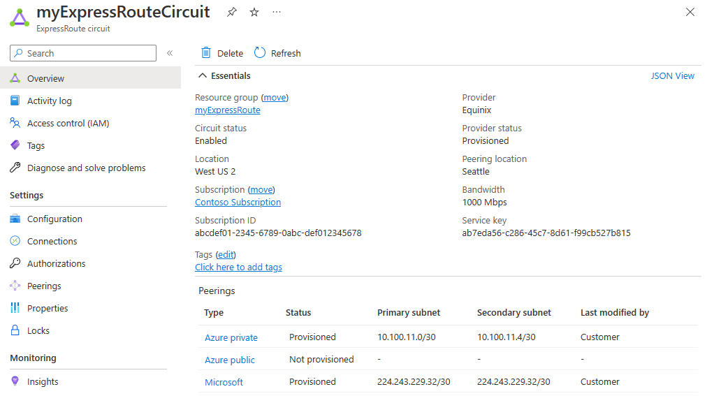
새 ExpressRoute 회로를 구성하려면 ExpressRoute 필수 구성 요소 문서 및 ExpressRoute 회로 만들기 및 수정을 차례로 시작합니다.
ExpressRoute 회로가 이미 있지만 Microsoft 피어링을 구성하지 않은 경우, ExpressRoute 회로에 대한 피어링 만들기 및 수정 문서를 사용하여 Microsoft 피어링을 구성합니다.
회로 및 Microsoft 피어링을 구성하면 Azure Portal에서 개요 페이지를 사용하여 쉽게 볼 수 있습니다.
2. 경로 필터 구성
경로 필터를 사용하면 ExpressRoute 회로의 Microsoft 피어링을 통해 사용하려는 서비스를 식별할 수 있습니다. 기본적으로 모든 BGP 커뮤니티 값의 허용 목록입니다.
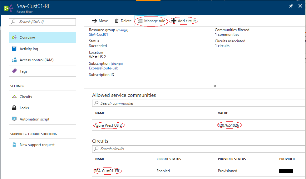
이 예제에서 배포는 Azure 미국 서부 2 지역에서만 이루어집니다. 경로 필터 규칙을 추가하여 Azure 미국 서부 2 지역별 접두사만 보여줍니다. 여기에는 BGP 커뮤니티 값 12076:51026이 있습니다. 규칙 관리를 선택하여 허용하려는 지역별 접두사를 지정합니다.
경로 필터 내에서 경로 필터가 적용되는 ExpressRoute 회로를 선택해야 합니다. 회로 추가를 선택하여 ExpressRoute 회로를 선택할 수 있습니다. 위의 그림에서 경로 필터는 예제 ExpressRoute 회로에 연결되어 있습니다.
2.1 경로 필터 구성
경로 필터를 구성합니다. 단계는 Microsoft 피어링용 경로 필터 구성을 참조하세요.
2.2 BGP 경로 확인
ExpressRoute 회로를 통해 Microsoft 피어링을 성공적으로 만들고 경로 필터를 해당 회로에 연결하면 MSEE(Microsoft Enterprise Edge)와 피어링된 PE 디바이스의 MSEE에서 수신된 BGP 경로를 확인할 수 있습니다. 유효성 검사 명령은 PE 디바이스의 운영 체제에 따라 달라집니다.
Cisco 예제
이 예제에서는 Cisco IOS-XE 명령을 사용합니다. 이 예제에서는 VRF(가상 라우팅 및 포워딩) 인스턴스를 사용하여 피어링 트래픽을 격리합니다.
show ip bgp vpnv4 vrf 10 summary
다음 부분 출력에서는 ASN(Autonomous System Number) 12076(MSEE)을 사용하여 68개의 접두사가 *.243.229.34 인접 항목에서 수신되었음을 보여 줍니다.
...

Neighbor        V           AS MsgRcvd MsgSent   TblVer  InQ OutQ Up/Down  State/PfxRcd
X.243.229.34    4        12076   17671   17650    25228    0    0 1w4d           68
인접 항목에서 수신된 접두사 목록을 보려면 다음 예제를 사용합니다.
sh ip bgp vpnv4 vrf 10 neighbors X.243.229.34 received-routes
올바른 일련의 접두사를 수신하고 있는지를 확인하려면 교차 확인을 실행할 수 있습니다. 다음 Azure PowerShell 명령 출력은 각 서비스 및 각 Azure 지역에 대한 Microsoft 피어링을 통해 보급된 접두사를 나열합니다.
Get-AzBgpServiceCommunity
3. VPN 게이트웨이 및 IPsec 터널 구성
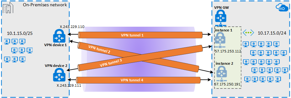
이 섹션에서는 Azure VPN Gateway와 온-프레미스 VPN 디바이스 간에 IPsec VPN 터널을 만듭니다. 예제에서는 Cisco 클라우드 서비스 라우터(CSR1000) VPN 디바이스를 사용합니다.
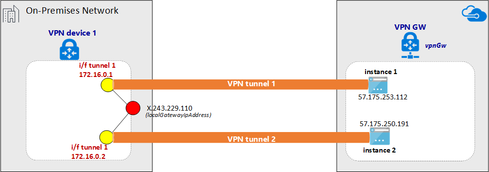
다음 다이어그램에서는 온-프레미스 VPN 디바이스 1과 Azure VPN Gateway 인스턴스 쌍 간에 설정된 IPsec VPN 터널을 보여 줍니다. 온-프레미스 VPN 디바이스 2와 Azure VPN Gateway 인스턴스 쌍 간에 설정된 두 개의 IPsec VPN 터널은 다이어그램에 표시되지 않습니다. 구성 세부 정보도 나열되지 않습니다. 그러나 추가 VPN 터널이 있다면 고가용성이 향상됩니다.
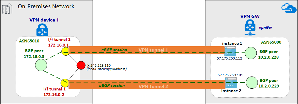
IPsec 터널 쌍을 통해 프라이빗 네트워크 경로를 교환하도록 eBGP 세션이 설정됩니다. 다음 다이어그램에서는 IPsec 터널 쌍을 통해 설정된 eBGP 세션을 보여줍니다.
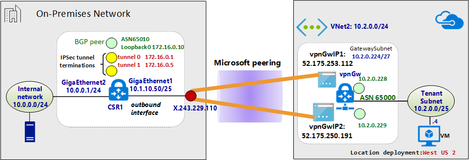
다음 다이어그램에서는 예제 네트워크의 추상화된 개요를 보여줍니다.
Azure Resource Manager 템플릿 예제 정보
이 예제에서는 Azure Resource Manager 템플릿을 사용하여 VPN Gateway 및 IPsec 터널이 종료되도록 구성됩니다. 처음 Resource Manager 템플릿을 사용하거나 Resource Manager 템플릿 기본 사항을 이해하려는 경우 Azure Resource Manager 템플릿의 구조 및 구문 이해를 참조하세요. 이 섹션의 템플릿은 아직 개발되지 않은 Azure 환경(가상 네트워크)을 만듭니다. 그러나 기존 가상 네트워크가 있는 경우 템플릿에서 참조할 수 있습니다. VPN Gateway IPsec/IKE 사이트 간 구성에 익숙하지 않은 경우 사이트 간 연결 만들기를 참조하세요.
참고 항목
이 구성을 만들기 위해 Azure Resource Manager 템플릿을 사용할 필요가 없습니다. Azure Portal 또는 PowerShell을 사용하여 이 구성을 만들 수 있습니다.
3.1 변수 선언
이 예제에서 변수 선언은 예제 네트워크에 따라 다릅니다. 변수를 선언할 때 사용자 환경을 반영하도록 이 섹션을 수정합니다.
- 변수 localAddressPrefix는 IPsec 터널을 종료하는 온-프레미스 IP 주소의 배열입니다.
- gatewaySku는 VPN 처리량을 결정합니다. gatewaySku 및 vpnType에 대한 자세한 내용은 VPN Gateway 구성 설정을 참조하세요. 가격 책정은 VPN Gateway 가격 책정을 참조하세요.
- vpnType을 RouteBased로 설정합니다.
"variables": {
  "virtualNetworkName": "SecureVNet",       // Name of the Azure VNet
  "azureVNetAddressPrefix": "10.2.0.0/24",  // Address space assigned to the VNet
  "subnetName": "Tenant",                   // subnet name in which tenants exists
  "subnetPrefix": "10.2.0.0/25",            // address space of the tenant subnet
  "gatewaySubnetPrefix": "10.2.0.224/27",   // address space of the gateway subnet
  "localGatewayName": "localGW1",           // name of remote gateway (on-premises)
  "localGatewayIpAddress": "X.243.229.110", // public IP address of the on-premises VPN device
  "localAddressPrefix": [
    "172.16.0.1/32",                        // termination of IPsec tunnel-1 on-premises
    "172.16.0.2/32"                         // termination of IPsec tunnel-2 on-premises
  ],
  "gatewayPublicIPName1": "vpnGwVIP1",    // Public address name of the first VPN gateway instance
  "gatewayPublicIPName2": "vpnGwVIP2",    // Public address name of the second VPN gateway instance
  "gatewayName": "vpnGw",                 // Name of the Azure VPN gateway
  "gatewaySku": "VpnGw1",                 // Azure VPN gateway SKU
  "vpnType": "RouteBased",                // type of VPN gateway
  "sharedKey": "string",                  // shared secret needs to match with on-premises configuration
  "asnVpnGateway": 65000,                 // BGP Autonomous System number assigned to the VPN Gateway
  "asnRemote": 65010,                     // BGP Autonmous Syste number assigned to the on-premises device
  "bgpPeeringAddress": "172.16.0.3",      // IP address of the remote BGP peer on-premises
  "connectionName": "vpn2local1",
  "vnetID": "[resourceId('Microsoft.Network/virtualNetworks', variables('virtualNetworkName'))]",
  "gatewaySubnetRef": "[concat(variables('vnetID'),'/subnets/','GatewaySubnet')]",
  "subnetRef": "[concat(variables('vnetID'),'/subnets/',variables('subnetName'))]",
  "api-version": "2017-06-01"
},
3.2 가상 네트워크 만들기(가상 네트워크)
기존 가상 네트워크를 VPN 터널과 연결하는 경우 이 단계를 건너뛸 수 있습니다.
{
  "apiVersion": "[variables('api-version')]",
  "type": "Microsoft.Network/virtualNetworks",
  "name": "[variables('virtualNetworkName')]",
  "location": "[resourceGroup().location]",
  "properties": {
    "addressSpace": {
      "addressPrefixes": [
        "[variables('azureVNetAddressPrefix')]"
      ]
    },
    "subnets": [
      {
        "name": "[variables('subnetName')]",
        "properties": {
          "addressPrefix": "[variables('subnetPrefix')]"
        }
      },
      {
        "name": "GatewaySubnet",
        "properties": {
          "addressPrefix": "[variables('gatewaySubnetPrefix')]"
        }
      }
    ]
  },
  "comments": "Create a Virtual Network with Subnet1 and Gatewaysubnet"
},
3.3 VPN 게이트웨이 인스턴스에 공용 IP 주소 할당
VPN Gateway의 각 인스턴스에 공용 IP 주소를 할당합니다.
{
  "apiVersion": "[variables('api-version')]",
  "type": "Microsoft.Network/publicIPAddresses",
    "name": "[variables('gatewayPublicIPName1')]",
    "location": "[resourceGroup().location]",
    "properties": {
      "publicIPAllocationMethod": "Dynamic"
    },
    "comments": "Public IP for the first instance of the VPN gateway"
  },
  {
    "apiVersion": "[variables('api-version')]",
    "type": "Microsoft.Network/publicIPAddresses",
    "name": "[variables('gatewayPublicIPName2')]",
    "location": "[resourceGroup().location]",
    "properties": {
      "publicIPAllocationMethod": "Dynamic"
    },
    "comments": "Public IP for the second instance of the VPN gateway"
  },
3.4 온-프레미스 VPN 터널 종료 지정(로컬 네트워크 게이트웨이)
온-프레미스 VPN 디바이스는 로컬 네트워크 게이트웨이라고 합니다. 다음 json 코드 조각은 원격 BGP 피어 세부 정보를 지정합니다.
{
  "apiVersion": "[variables('api-version')]",
  "type": "Microsoft.Network/localNetworkGateways",
  "name": "[variables('localGatewayName')]",
  "location": "[resourceGroup().location]",
  "properties": {
    "localNetworkAddressSpace": {
      "addressPrefixes": "[variables('localAddressPrefix')]"
    },
    "gatewayIpAddress": "[variables('localGatewayIpAddress')]",
    "bgpSettings": {
      "asn": "[variables('asnRemote')]",
      "bgpPeeringAddress": "[variables('bgpPeeringAddress')]",
      "peerWeight": 0
    }
  },
  "comments": "Local Network Gateway (referred to your on-premises location) with IP address of remote tunnel peering and IP address of remote BGP peer"
},
3.5. VPN 게이트웨이 만들기
템플릿의 이 섹션은 활성-활성 구성에 대한 필수 설정으로 VPN Gateway를 구성합니다. 다음 요구 사항을 고려하세요.
- "RouteBased" VpnType을 사용하여 VPN Gateway를 만듭니다. 이 설정은 VPN Gateway와 VPN 온-프레미스 간에 BGP 라우팅을 사용하도록 설정하려는 경우에 필수입니다.
- 활성-활성 모드에서 VPN Gateway의 두 인스턴스와 지정된 온-프레미스 디바이스 간에 VPN 터널을 설정하려면 Resource Manager 템플릿에서 "activeActive" 매개 변수를 true로 설정합니다. 고가용성 VPN Gateway에 대한 자세한 정보를 이해하려면 고가용성 VPN Gateway 연결을 참조하세요.
- VPN 터널 간에 eBGP 세션을 구성하려면 양쪽에 두 개의 다른 ASN을 지정해야 합니다. 프라이빗 ASN 번호를 지정하는 것이 좋습니다. 자세한 내용은 BGP 및 Azure VPN Gateway 개요를 참조하세요.
{
"apiVersion": "[variables('api-version')]",
"type": "Microsoft.Network/virtualNetworkGateways",
"name": "[variables('gatewayName')]",
"location": "[resourceGroup().location]",
"dependsOn": [
  "[concat('Microsoft.Network/publicIPAddresses/', variables('gatewayPublicIPName1'))]",
  "[concat('Microsoft.Network/publicIPAddresses/', variables('gatewayPublicIPName2'))]",
  "[concat('Microsoft.Network/virtualNetworks/', variables('virtualNetworkName'))]"
],
"properties": {
  "ipConfigurations": [
    {
      "properties": {
        "privateIPAllocationMethod": "Dynamic",
        "subnet": {
          "id": "[variables('gatewaySubnetRef')]"
        },
        "publicIPAddress": {
          "id": "[resourceId('Microsoft.Network/publicIPAddresses',variables('gatewayPublicIPName1'))]"
        }
      },
      "name": "vnetGtwConfig1"
    },
    {
      "properties": {
        "privateIPAllocationMethod": "Dynamic",
        "subnet": {
          "id": "[variables('gatewaySubnetRef')]"
        },
        "publicIPAddress": {
          "id": "[resourceId('Microsoft.Network/publicIPAddresses',variables('gatewayPublicIPName2'))]"
        }
      },
          "name": "vnetGtwConfig2"
        }
      ],
      "sku": {
        "name": "[variables('gatewaySku')]",
        "tier": "[variables('gatewaySku')]"
      },
      "gatewayType": "Vpn",
      "vpnType": "[variables('vpnType')]",
      "enableBgp": true,
      "activeActive": true,
      "bgpSettings": {
        "asn": "[variables('asnVpnGateway')]"
      }
    },
    "comments": "VPN Gateway in active-active configuration with BGP support"
  },
3.6 IPsec 터널 설정
스크립트의 최종 작업에서는 Azure VPN Gateway와 온-프레미스 VPN 디바이스 간에 IPsec 터널을 만듭니다.
{
  "apiVersion": "[variables('api-version')]",
  "name": "[variables('connectionName')]",
  "type": "Microsoft.Network/connections",
  "location": "[resourceGroup().location]",
  "dependsOn": [
    "[concat('Microsoft.Network/virtualNetworkGateways/', variables('gatewayName'))]",
    "[concat('Microsoft.Network/localNetworkGateways/', variables('localGatewayName'))]"
  ],
  "properties": {
    "virtualNetworkGateway1": {
      "id": "[resourceId('Microsoft.Network/virtualNetworkGateways', variables('gatewayName'))]"
    },
    "localNetworkGateway2": {
      "id": "[resourceId('Microsoft.Network/localNetworkGateways', variables('localGatewayName'))]"
    },
    "connectionType": "IPsec",
    "routingWeight": 0,
    "sharedKey": "[variables('sharedKey')]",
    "enableBGP": "true"
  },
  "comments": "Create a Connection type site-to-site (IPsec) between the Azure VPN Gateway and the VPN device on-premises"
  }
4. 온-프레미스 VPN 디바이스 구성
Azure VPN Gateway는 여러 공급 업체의 여러 VPN 디바이스와 호환됩니다. 구성 정보 및 VPN Gateway에서 작동하도록 확인된 디바이스는 VPN 디바이스 정보를 참조하세요.
VPN 디바이스를 구성할 때 다음 항목이 필요합니다.
- 공유 키. 이 값은 사이트 간 VPN 연결을 만들 때 지정하는 것과 동일한 공유 키입니다. 이 예제에서는 기본적인 공유 키를 사용합니다. 실제로 사용할 키는 좀 더 복잡하게 생성하는 것이 좋습니다.
- VPN Gateway의 공용 IP 주소 - Azure Portal, PowerShell 또는 CLI를 사용하여 공용 IP 주소를 볼 수 있습니다. Azure Portal을 사용하여 VPN 게이트웨이의 공용 IP 주소를 찾으려면 가상 네트워크 게이트웨이로 이동한 다음, 게이트웨이의 이름을 선택합니다.
일반적으로 eBGP 피어는 직접 연결됩니다(종종 WAN 연결을 통해). 그러나 ExpressRoute Microsoft 피어링을 통해 IPsec VPN 터널에 eBGP를 구성하는 경우 eBGP 피어 간에 여러 라우팅 도메인이 있습니다. 직접 연결되지 않은 두 개의 피어 간에 eBGP 인접 관계를 설정하려면 ebgp-multihop 명령을 사용합니다. ebgp-multihop 명령 뒤에 오는 정수는 BGP 패킷에서 TTL(Time to Live) 값을 지정합니다. maximum-paths eibgp 2 명령은 두 개의 BGP 경로 간에 트래픽 부하를 분산할 수 있습니다.
Cisco CSR1000 예제
다음 예제에서는 온-프레미스 VPN 디바이스인 Hyper-V 가상 머신에서 Cisco CSR1000에 대한 구성을 보여줍니다.
!
crypto ikev2 proposal az-PROPOSAL
 encryption aes-cbc-256 aes-cbc-128 3des
 integrity sha1
 group 2
!
crypto ikev2 policy az-POLICY
 proposal az-PROPOSAL
!
crypto ikev2 keyring key-peer1
 peer azvpn1
  address 52.175.253.112
  pre-shared-key secret*1234
 !
!
crypto ikev2 keyring key-peer2
 peer azvpn2
  address 52.175.250.191
  pre-shared-key secret*1234
 !
!
!
crypto ikev2 profile az-PROFILE1
 match address local interface GigabitEthernet1
 match identity remote address 52.175.253.112 255.255.255.255
 authentication remote pre-share
 authentication local pre-share
 keyring local key-peer1
!
crypto ikev2 profile az-PROFILE2
 match address local interface GigabitEthernet1
 match identity remote address 52.175.250.191 255.255.255.255
 authentication remote pre-share
 authentication local pre-share
 keyring local key-peer2
!
crypto ikev2 dpd 10 2 on-demand
!
!
crypto ipsec transform-set az-IPSEC-PROPOSAL-SET esp-aes 256 esp-sha-hmac
 mode tunnel
!
crypto ipsec profile az-VTI1
 set transform-set az-IPSEC-PROPOSAL-SET
 set ikev2-profile az-PROFILE1
!
crypto ipsec profile az-VTI2
 set transform-set az-IPSEC-PROPOSAL-SET
 set ikev2-profile az-PROFILE2
!
!
interface Loopback0
 ip address 172.16.0.3 255.255.255.255
!
interface Tunnel0
 ip address 172.16.0.1 255.255.255.255
 ip tcp adjust-mss 1350
 tunnel source GigabitEthernet1
 tunnel mode ipsec ipv4
 tunnel destination 52.175.253.112
 tunnel protection ipsec profile az-VTI1
!
interface Tunnel1
 ip address 172.16.0.2 255.255.255.255
 ip tcp adjust-mss 1350
 tunnel source GigabitEthernet1
 tunnel mode ipsec ipv4
 tunnel destination 52.175.250.191
 tunnel protection ipsec profile az-VTI2
!
interface GigabitEthernet1
 description External interface
 ip address x.243.229.110 255.255.255.252
 negotiation auto
 no mop enabled
 no mop sysid
!
interface GigabitEthernet2
 ip address 10.0.0.1 255.255.255.0
 negotiation auto
 no mop enabled
 no mop sysid
!
router bgp 65010
 bgp router-id interface Loopback0
 bgp log-neighbor-changes
 network 10.0.0.0 mask 255.255.255.0
 network 10.1.10.0 mask 255.255.255.128
 neighbor 10.2.0.228 remote-as 65000
 neighbor 10.2.0.228 ebgp-multihop 5
 neighbor 10.2.0.228 update-source Loopback0
 neighbor 10.2.0.228 soft-reconfiguration inbound
 neighbor 10.2.0.228 filter-list 10 out
 neighbor 10.2.0.229 remote-as 65000
 neighbor 10.2.0.229 ebgp-multihop 5
 neighbor 10.2.0.229 update-source Loopback0
 neighbor 10.2.0.229 soft-reconfiguration inbound
 maximum-paths eibgp 2
!
ip route 0.0.0.0 0.0.0.0 10.1.10.1
ip route 10.2.0.228 255.255.255.255 Tunnel0
ip route 10.2.0.229 255.255.255.255 Tunnel1
!
5. VPN 디바이스 필터링 및 방화벽 구성(선택 사항)
요구 사항에 따라 방화벽 및 필터링을 구성합니다.
6. IPsec 터널 테스트 및 유효성 검사
IPsec 터널의 상태는 PowerShell 명령을 사용하여 Azure VPN Gateway에서 확인할 수 있습니다.
Get-AzVirtualNetworkGatewayConnection -Name vpn2local1 -ResourceGroupName myRG | Select-Object ConnectionStatus,EgressBytesTransferred,IngressBytesTransferred | fl
예제 출력:
ConnectionStatus        : Connected
EgressBytesTransferred  : 17734660
IngressBytesTransferred : 10538211
Azure VPN Gateway 인스턴스에서 터널 상태를 독립적으로 확인하려면 다음 예제를 사용합니다.
Get-AzVirtualNetworkGatewayConnection -Name vpn2local1 -ResourceGroupName myRG | Select-Object -ExpandProperty TunnelConnectionStatus
예제 출력:
Tunnel                           : vpn2local1_52.175.250.191
ConnectionStatus                 : Connected
IngressBytesTransferred          : 4877438
EgressBytesTransferred           : 8754071
LastConnectionEstablishedUtcTime : 11/04/2017 17:03:30

Tunnel                           : vpn2local1_52.175.253.112
ConnectionStatus                 : Connected
IngressBytesTransferred          : 5660773
EgressBytesTransferred           : 8980589
LastConnectionEstablishedUtcTime : 11/04/2017 17:03:13
또한 온-프레미스 VPN 디바이스에서 터널 상태를 확인할 수 있습니다.
Cisco CSR1000 예제:
show crypto session detail
show crypto ikev2 sa
show crypto ikev2 session detail
show crypto ipsec sa
예제 출력:
csr1#show crypto session detail

Crypto session current status

Code: C - IKE Configuration mode, D - Dead Peer Detection
K - Keepalives, N - NAT-traversal, T - cTCP encapsulation
X - IKE Extended Authentication, F - IKE Fragmentation
R - IKE Auto Reconnect

Interface: Tunnel1
Profile: az-PROFILE2
Uptime: 00:52:46
Session status: UP-ACTIVE
Peer: 52.175.250.191 port 4500 fvrf: (none) ivrf: (none)
      Phase1_id: 52.175.250.191
      Desc: (none)
  Session ID: 3
  IKEv2 SA: local 10.1.10.50/4500 remote 52.175.250.191/4500 Active
          Capabilities:DN connid:3 lifetime:23:07:14
  IPSEC FLOW: permit ip 0.0.0.0/0.0.0.0 0.0.0.0/0.0.0.0
        Active SAs: 2, origin: crypto map
        Inbound:  #pkts dec'ed 279 drop 0 life (KB/Sec) 4607976/433
        Outbound: #pkts enc'ed 164 drop 0 life (KB/Sec) 4607992/433

Interface: Tunnel0
Profile: az-PROFILE1
Uptime: 00:52:43
Session status: UP-ACTIVE
Peer: 52.175.253.112 port 4500 fvrf: (none) ivrf: (none)
      Phase1_id: 52.175.253.112
      Desc: (none)
  Session ID: 2
  IKEv2 SA: local 10.1.10.50/4500 remote 52.175.253.112/4500 Active
          Capabilities:DN connid:2 lifetime:23:07:17
  IPSEC FLOW: permit ip 0.0.0.0/0.0.0.0 0.0.0.0/0.0.0.0
        Active SAs: 2, origin: crypto map
        Inbound:  #pkts dec'ed 668 drop 0 life (KB/Sec) 4607926/437
        Outbound: #pkts enc'ed 477 drop 0 life (KB/Sec) 4607953/437
VTI(가상 터널 인터페이스)에서 회선 프로토콜은 IKE 단계 2가 완료될 때까지 ‘up’으로 변경되지 않습니다. 다음 명령은 보안 연결을 확인합니다.
csr1#show crypto ikev2 sa

IPv4 Crypto IKEv2  SA

Tunnel-id Local                 Remote                fvrf/ivrf            Status
2         10.1.10.50/4500       52.175.253.112/4500   none/none            READY
      Encr: AES-CBC, keysize: 256, PRF: SHA1, Hash: SHA96, DH Grp:2, Auth sign: PSK, Auth verify: PSK
      Life/Active Time: 86400/3277 sec

Tunnel-id Local                 Remote                fvrf/ivrf            Status
3         10.1.10.50/4500       52.175.250.191/4500   none/none            READY
      Encr: AES-CBC, keysize: 256, PRF: SHA1, Hash: SHA96, DH Grp:2, Auth sign: PSK, Auth verify: PSK
      Life/Active Time: 86400/3280 sec

IPv6 Crypto IKEv2  SA

csr1#show crypto ipsec sa | inc encaps|decaps
    #pkts encaps: 177, #pkts encrypt: 177, #pkts digest: 177
    #pkts decaps: 296, #pkts decrypt: 296, #pkts verify: 296
    #pkts encaps: 554, #pkts encrypt: 554, #pkts digest: 554
    #pkts decaps: 746, #pkts decrypt: 746, #pkts verify: 746
내부 네트워크 온-프레미스와 Azure 가상 네트워크 간에 엔드투엔드 연결 확인
IPsec 터널이 실행 중이고 고정 경로가 정확하게 설정되어 있는 경우 원격 BGP 피어의 IP 주소를 ping할 수 있습니다.
csr1#ping 10.2.0.228
Type escape sequence to abort.
Sending 5, 100-byte ICMP Echos to 10.2.0.228, timeout is 2 seconds:
!!!!!
Success rate is 100 percent (5/5), round-trip min/avg/max = 5/5/5 ms

#ping 10.2.0.229
Type escape sequence to abort.
Sending 5, 100-byte ICMP Echos to 10.2.0.229, timeout is 2 seconds:
!!!!!
Success rate is 100 percent (5/5), round-trip min/avg/max = 4/5/6 ms
IPsec을 통한 BGP 세션 확인
Azure VPN Gateway에서 BGP 피어의 상태를 확인합니다.
Get-AzVirtualNetworkGatewayBGPPeerStatus -VirtualNetworkGatewayName vpnGtw -ResourceGroupName SEA-C1-VPN-ER | ft
예제 출력:
  Asn ConnectedDuration LocalAddress MessagesReceived MessagesSent Neighbor    RoutesReceived State
  --- ----------------- ------------ ---------------- ------------ --------    -------------- -----
65010 00:57:19.9003584  10.2.0.228               68           72   172.16.0.10              2 Connected
65000                   10.2.0.228                0            0   10.2.0.228               0 Unknown
65000 07:13:51.0109601  10.2.0.228              507          500   10.2.0.229               6 Connected
VPN 집선 장치 온-프레미스에서 eBGP를 통해 수신된 네트워크 접두사 목록을 확인하려면 "Origin" 특성으로 필터링하면 됩니다.
Get-AzVirtualNetworkGatewayLearnedRoute -VirtualNetworkGatewayName vpnGtw -ResourceGroupName myRG | Where-Object Origin -eq "EBgp" |ft
예제 출력에서 ASN 65010은 VPN 온-프레미스의 BGP 익명 시스템 번호입니다.
AsPath LocalAddress Network      NextHop     Origin SourcePeer  Weight
------ ------------ -------      -------     ------ ----------  ------
65010  10.2.0.228   10.1.10.0/25 172.16.0.10 EBgp   172.16.0.10  32768
65010  10.2.0.228   10.0.0.0/24  172.16.0.10 EBgp   172.16.0.10  32768
보급된 경로 목록 보기:
Get-AzVirtualNetworkGatewayAdvertisedRoute -VirtualNetworkGatewayName vpnGtw -ResourceGroupName myRG -Peer 10.2.0.228 | ft
예제 출력:
AsPath LocalAddress Network        NextHop    Origin SourcePeer Weight
------ ------------ -------        -------    ------ ---------- ------
       10.2.0.229   10.2.0.0/24    10.2.0.229 Igp                  0
       10.2.0.229   172.16.0.10/32 10.2.0.229 Igp                  0
       10.2.0.229   172.16.0.5/32  10.2.0.229 Igp                  0
       10.2.0.229   172.16.0.1/32  10.2.0.229 Igp                  0
65010  10.2.0.229   10.1.10.0/25   10.2.0.229 Igp                  0
65010  10.2.0.229   10.0.0.0/24    10.2.0.229 Igp                  0
온-프레미스 Cisco CSR1000의 예제:
csr1#show ip bgp neighbors 10.2.0.228 routes
BGP table version is 7, local router ID is 172.16.0.10
Status codes: s suppressed, d damped, h history, * valid, > best, i - internal,
              r RIB-failure, S Stale, m multipath, b backup-path, f RT-Filter,
              x best-external, a additional-path, c RIB-compressed,
              t secondary path,
Origin codes: i - IGP, e - EGP, ? - incomplete
RPKI validation codes: V valid, I invalid, N Not found

     Network          Next Hop            Metric LocPrf Weight Path
 *>   10.2.0.0/24      10.2.0.228                             0 65000 i
 r>   172.16.0.1/32    10.2.0.228                             0 65000 i
 r>   172.16.0.2/32    10.2.0.228                             0 65000 i
 r>   172.16.0.3/32   10.2.0.228                             0 65000 i

Total number of prefixes 4
온-프레미스 Cisco CSR1000에서 Azure VPN Gateway로 보급된 네트워크 목록을 나열하려면 다음 명령을 사용합니다.
csr1#show ip bgp neighbors 10.2.0.228 advertised-routes
BGP table version is 7, local router ID is 172.16.0.10
Status codes: s suppressed, d damped, h history, * valid, > best, i - internal,
              r RIB-failure, S Stale, m multipath, b backup-path, f RT-Filter,
              x best-external, a additional-path, c RIB-compressed,
              t secondary path,
Origin codes: i - IGP, e - EGP, ? - incomplete
RPKI validation codes: V valid, I invalid, N Not found

     Network          Next Hop            Metric LocPrf Weight Path
 *>   10.0.0.0/24      0.0.0.0                  0         32768 i
 *>   10.1.10.0/25     0.0.0.0                  0         32768 i

Total number of prefixes 2