Dependency diagrams: reference
Applies to: ![]() Visual Studio
Visual Studio ![]() Visual Studio for Mac
Visual Studio for Mac
Note
This article applies to Visual Studio 2017. If you're looking for the latest Visual Studio documentation, see Visual Studio documentation. We recommend upgrading to the latest version of Visual Studio. Download it here
In Visual Studio, you can use a dependency diagram to visualize the high-level, logical architecture of your system. A dependency diagram organizes the physical artifacts in your system into logical, abstract groups called layers. These layers describe major tasks that the artifacts perform or the major components of your system. Each layer can also contain nested layers that describe more detailed tasks.
To see which editions of Visual Studio support this feature, see Edition support for architecture and modeling tools.
Note
Dependency diagrams for .NET Core projects are supported starting in Visual Studio 2019 version 16.2.
You can specify the intended or existing dependencies between layers. These dependencies, which are represented as arrows, indicate which layers can use or currently use the functionality represented by other layers. By organizing your system into layers that describe distinct roles and functions, a dependency diagram can help make it easier for you to understand, reuse, and maintain your code.
Use a dependency diagram to help you perform the following tasks:
Communicate the existing or intended logical architecture of your system.
Discover conflicts between your existing code and the intended architecture.
Visualize the impact of changes on the intended architecture when you refactor, update, or evolve your system.
Reinforce the intended architecture during the development and maintenance of your code by including validation with your check-in and build operations.
This topic describes the elements that you can use on a dependency diagram. For more detailed information about how to create and draw dependency diagrams, see Dependency Diagrams: Guidelines. For more information about layering patterns, visit the Patterns & Practices site.
Reading dependency diagrams
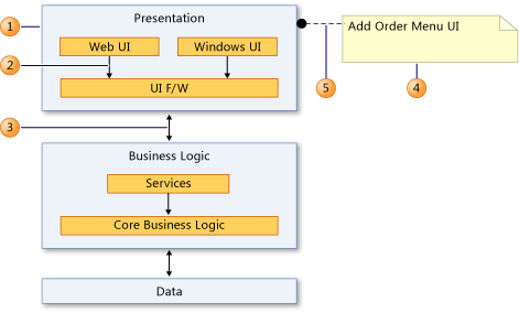
The following table describes the elements that you can use on a dependency diagram.
| Shape | Element | Description |
|---|---|---|
| 1 | Layer | A logical group of physical artifacts in your system. These artifacts can be namespaces, projects, classes, methods, and so on. To see the artifacts that are linked to a layer, open the shortcut menu for the layer, and then choose View Links to open Layer Explorer. For more information, see Layer Explorer. - Forbidden Namespace Dependencies - Specifies that artifacts associated with this layer cannot depend on the specified namespaces. - Forbidden Namespaces - Specifies that artifacts associated with this layer must not belong to the specified namespaces. - Required Namespaces - Specifies that artifacts associated with this layer must belong to one of the specified namespaces. |
| 2 | Dependency | Indicates that one layer can use the functionality in another layer, but not vice versa. - Direction - Specifies the direction of the dependency. |
| 3 | Bidirectional Dependency | Indicates that one layer can use the functionality in another layer, and vice versa. - Direction - Specifies the direction of the dependency. |
| 4 | Comment | Use to add general notes to the diagram or elements on the diagram. |
| 5 | Comment Link | Use to link comments to elements on the diagram. |
Layer Explorer
You can link each layer to artifacts in your solution, such as projects, classes, namespaces, project files, and other parts of your software. The number on a layer shows the number of artifacts that are linked to the layer. However, when reading the number of artifacts on a layer, remember the following:
If a layer links to an artifact that contains other artifacts, but the layer does not link directly to the other artifacts, then the number includes only the linked artifact. However, the other artifacts are included for analysis during layer validation.
For example, if a layer is linked to a single namespace, then the number of linked artifacts is 1, even if the namespace contains classes. If the layer also has links to each class in the namespace, then the number will include the linked classes.
If a layer contains other layers that are linked to artifacts, then the container layer is also linked to those artifacts, even though the number on the container layer does not include those artifacts.
For more information about linking layers and artifacts, see:
Examine the linked artifacts
On the dependency diagram, open the shortcut menu for one or more layers, and then choose View Links.
Layer Explorer opens and shows the artifacts that are linked to the selected layers. Layer Explorer has a column that shows each of the properties of the artifact links.
Note
If you cannot see all of these properties, expand the Layer Explorer window.
| Column in Layer Explorer | Description |
|---|---|
| Categories | The kind of artifact, such as a class, namespace, source file, and so on |
| Layer | The layer that links to the artifact |
| Supports Validation | If True, then the layer validation process can verify that the project conforms to dependencies to or from this element. If False, then the link does not participate in the layer validation process. For more information, see Dependency Diagrams: Guidelines. |
| Identifier | The reference to the linked artifact |