支援螢幕方向 (DirectX 和 C++)
您處理 DisplayInformation::OrientationChanged 事件時,通用 Windows 平台 (UWP) 應用程式可支援多個螢幕方向。 本文將介紹在 UWP DirectX 應用程式中處理螢幕旋轉的最佳做法,有助於快速有效地使用 Windows 10 裝置的圖形硬體。
開始之前,別忘了不論裝置方向為何,圖形硬體一律會以同個方式輸出像素資料。 Windows 10 裝置可決定其目前的顯示方向 (使用某種感應器或軟體切換開關),並允許使用者變更顯示設定。 因此,Windows 10 本身就會處理影像旋轉,以確保影像依裝置方向「直立」。 根據預設,應用程式會收到某項目 (例如視窗大小) 已變更方向的通知。 發生此情況時,Windows 10 會立即旋轉影像以進行最終顯示。 針對四個特定螢幕方向中的三個方向 (稍後會說明),Windows 10 會使用額外的圖形資源和計算作業以顯示最終影像。
針對 UWP DirectX 應用程式,DisplayInformation 物件會提供可讓應用程式查詢的基本顯示方向資料。 預設方向為橫向,其中顯示器的像素寬度大於高度;替代方向為直向,其中顯示器畫面會旋轉 90 度 (任一方向),寬度則會小於高度。
Windows 10 會定義四種特定的顯示方向模式:
- 橫向 — Windows 10 的預設顯示方向,並視為旋轉的基礎或初始角度 (0 度)。
- 直向 — 顯示器順時針旋轉 90 度 (或逆時針旋轉 270 度)。
- 橫向翻轉 — 顯示器旋轉 180 度 (上下顛倒)。
- 直向翻轉 — 顯示器順時針旋轉 270 度 (或逆時針旋轉 90 度)。
當顯示器從一個方向旋轉到另一個方向時,Windows 10 會在內部執行旋轉作業,以將繪製的影像與新的方向對齊,而使用者會在畫面上看到直立影像。
此外,切換方向時,Windows 10 也會顯示自動轉換動畫,以建立順暢的使用者體驗。 顯示方向改變時,使用者會看到固定縮放比例的顯示畫面影像及其旋轉動畫。 Windows 10 會分配時間給應用程式進行新方向的配置。
整體而言,這是處理螢幕方向變更的一般程序:
- 使用視窗界限值和顯示方向資料的組合,讓交換鏈結與裝置的原生顯示方向保持一致。
- 使用 IDXGISwapChain1::SetRotation 通知 Windows 10 交換鏈結的方向。
- 變更轉譯程式碼,以產生與裝置使用者方向一致的影像。
調整交換鏈結的大小,並預先旋轉其內容
若要在 UWP DirectX 應用程式中執行基本的顯示大小調整,並預先旋轉其內容,請實作下列步驟:
- 處理 DisplayInformation::OrientationChanged 事件。
- 將交換鏈結調整為視窗的新大小。
- 呼叫 IDXGISwapChain1::SetRotation 以設定交換鏈結的方向。
- 重新建立任何相依於視窗大小的資源,例如:轉譯目標及其他像素資料緩衝區。
接著我們來進一步說明這些步驟。
第一步是註冊 DisplayInformation::OrientationChanged 事件的處理常式。 每次螢幕方向變更時 (例如顯示器旋轉),應用程式都會引發此事件。
若要處理 DisplayInformation::OrientationChanged 事件,請在以下必要的方法中連結 DisplayInformation::OrientationChanged 的處理常式:SetWindow 方法 (此為 IFrameworkView 介面的方法之一,檢視服務提供者必須實作該介面)。
在此程式碼範例中,DisplayInformation::OrientationChanged 的事件處理常式是一個稱為 OnOrientationChanged 的方法。 DisplayInformation::OrientationChanged 引發後會依序呼叫 SetCurrentOrientation 方法,而該方法則會接著呼叫 CreateWindowSizeDependentResources。
void App::SetWindow(CoreWindow^ window)
{
  // ... Other UI event handlers assigned here ...

    currentDisplayInformation->OrientationChanged +=
        ref new TypedEventHandler<DisplayInformation^, Object^>(this, &App::OnOrientationChanged);

  // ...
}
}
void App::OnOrientationChanged(DisplayInformation^ sender, Object^ args)
{
    m_deviceResources->SetCurrentOrientation(sender->CurrentOrientation);
    m_main->CreateWindowSizeDependentResources();
}

// This method is called in the event handler for the OrientationChanged event.
void DX::DeviceResources::SetCurrentOrientation(DisplayOrientations currentOrientation)
{
    if (m_currentOrientation != currentOrientation)
    {
        m_currentOrientation = currentOrientation;
        CreateWindowSizeDependentResources();
    }
}
接下來,您可以調整新螢幕方向的交換鏈結大小,並準備在執行轉譯時旋轉圖形管線的內容。 在此範例中,DirectXBase::CreateWindowSizeDependentResources 方法用來處理以下作業:呼叫 IDXGISwapChain::ResizeBuffers、設定 3D 和 2D 旋轉矩陣、呼叫 SetRotation 及重新建立資源。
void DX::DeviceResources::CreateWindowSizeDependentResources()
{
    // Clear the previous window size specific context.
    ID3D11RenderTargetView* nullViews[] = {nullptr};
    m_d3dContext->OMSetRenderTargets(ARRAYSIZE(nullViews), nullViews, nullptr);
    m_d3dRenderTargetView = nullptr;
    m_d2dContext->SetTarget(nullptr);
    m_d2dTargetBitmap = nullptr;
    m_d3dDepthStencilView = nullptr;
    m_d3dContext->Flush();

    // Calculate the necessary render target size in pixels.
    m_outputSize.Width = DX::ConvertDipsToPixels(m_logicalSize.Width, m_dpi);
    m_outputSize.Height = DX::ConvertDipsToPixels(m_logicalSize.Height, m_dpi);

    // Prevent zero size DirectX content from being created.
    m_outputSize.Width = max(m_outputSize.Width, 1);
    m_outputSize.Height = max(m_outputSize.Height, 1);

    // The width and height of the swap chain must be based on the window's
    // natively-oriented width and height. If the window is not in the native
    // orientation, the dimensions must be reversed.
    DXGI_MODE_ROTATION displayRotation = ComputeDisplayRotation();

    bool swapDimensions = displayRotation == DXGI_MODE_ROTATION_ROTATE90 || displayRotation == DXGI_MODE_ROTATION_ROTATE270;
    m_d3dRenderTargetSize.Width = swapDimensions ? m_outputSize.Height : m_outputSize.Width;
    m_d3dRenderTargetSize.Height = swapDimensions ? m_outputSize.Width : m_outputSize.Height;

    if (m_swapChain != nullptr)
    {
        // If the swap chain already exists, resize it.
        HRESULT hr = m_swapChain->ResizeBuffers(
            2, // Double-buffered swap chain.
            lround(m_d3dRenderTargetSize.Width),
            lround(m_d3dRenderTargetSize.Height),
            DXGI_FORMAT_B8G8R8A8_UNORM,
            0
            );

        if (hr == DXGI_ERROR_DEVICE_REMOVED || hr == DXGI_ERROR_DEVICE_RESET)
        {
            // If the device was removed for any reason, a new device and swap chain will need to be created.
            HandleDeviceLost();

            // Everything is set up now. Do not continue execution of this method. HandleDeviceLost will reenter this method
            // and correctly set up the new device.
            return;
        }
        else
        {
            DX::ThrowIfFailed(hr);
        }
    }
    else
    {
        // Otherwise, create a new one using the same adapter as the existing Direct3D device.
        DXGI_SWAP_CHAIN_DESC1 swapChainDesc = {0};

        swapChainDesc.Width = lround(m_d3dRenderTargetSize.Width); // Match the size of the window.
        swapChainDesc.Height = lround(m_d3dRenderTargetSize.Height);
        swapChainDesc.Format = DXGI_FORMAT_B8G8R8A8_UNORM; // This is the most common swap chain format.
        swapChainDesc.Stereo = false;
        swapChainDesc.SampleDesc.Count = 1; // Don't use multi-sampling.
        swapChainDesc.SampleDesc.Quality = 0;
        swapChainDesc.BufferUsage = DXGI_USAGE_RENDER_TARGET_OUTPUT;
        swapChainDesc.BufferCount = 2; // Use double-buffering to minimize latency.
        swapChainDesc.SwapEffect = DXGI_SWAP_EFFECT_FLIP_SEQUENTIAL; // All UWP apps must use this SwapEffect.
        swapChainDesc.Flags = 0;
        swapChainDesc.Scaling = DXGI_SCALING_NONE;
        swapChainDesc.AlphaMode = DXGI_ALPHA_MODE_IGNORE;

        // This sequence obtains the DXGI factory that was used to create the Direct3D device above.
        ComPtr<IDXGIDevice3> dxgiDevice;
        DX::ThrowIfFailed(
            m_d3dDevice.As(&dxgiDevice)
            );

        ComPtr<IDXGIAdapter> dxgiAdapter;
        DX::ThrowIfFailed(
            dxgiDevice->GetAdapter(&dxgiAdapter)
            );

        ComPtr<IDXGIFactory2> dxgiFactory;
        DX::ThrowIfFailed(
            dxgiAdapter->GetParent(IID_PPV_ARGS(&dxgiFactory))
            );

        DX::ThrowIfFailed(
            dxgiFactory->CreateSwapChainForCoreWindow(
                m_d3dDevice.Get(),
                reinterpret_cast<IUnknown*>(m_window.Get()),
                &swapChainDesc,
                nullptr,
                &m_swapChain
                )
            );

        // Ensure that DXGI does not queue more than one frame at a time. This both reduces latency and
        // ensures that the application will only render after each VSync, minimizing power consumption.
        DX::ThrowIfFailed(
            dxgiDevice->SetMaximumFrameLatency(1)
            );
    }

    // Set the proper orientation for the swap chain, and generate 2D and
    // 3D matrix transformations for rendering to the rotated swap chain.
    // Note the rotation angle for the 2D and 3D transforms are different.
    // This is due to the difference in coordinate spaces.  Additionally,
    // the 3D matrix is specified explicitly to avoid rounding errors.

    switch (displayRotation)
    {
    case DXGI_MODE_ROTATION_IDENTITY:
        m_orientationTransform2D = Matrix3x2F::Identity();
        m_orientationTransform3D = ScreenRotation::Rotation0;
        break;

    case DXGI_MODE_ROTATION_ROTATE90:
        m_orientationTransform2D =
            Matrix3x2F::Rotation(90.0f) *
            Matrix3x2F::Translation(m_logicalSize.Height, 0.0f);
        m_orientationTransform3D = ScreenRotation::Rotation270;
        break;

    case DXGI_MODE_ROTATION_ROTATE180:
        m_orientationTransform2D =
            Matrix3x2F::Rotation(180.0f) *
            Matrix3x2F::Translation(m_logicalSize.Width, m_logicalSize.Height);
        m_orientationTransform3D = ScreenRotation::Rotation180;
        break;

    case DXGI_MODE_ROTATION_ROTATE270:
        m_orientationTransform2D =
            Matrix3x2F::Rotation(270.0f) *
            Matrix3x2F::Translation(0.0f, m_logicalSize.Width);
        m_orientationTransform3D = ScreenRotation::Rotation90;
        break;

    default:
        throw ref new FailureException();
    }


    //SDM: only instance of SetRotation
    DX::ThrowIfFailed(
        m_swapChain->SetRotation(displayRotation)
        );

    // Create a render target view of the swap chain back buffer.
    ComPtr<ID3D11Texture2D> backBuffer;
    DX::ThrowIfFailed(
        m_swapChain->GetBuffer(0, IID_PPV_ARGS(&backBuffer))
        );

    DX::ThrowIfFailed(
        m_d3dDevice->CreateRenderTargetView(
            backBuffer.Get(),
            nullptr,
            &m_d3dRenderTargetView
            )
        );

    // Create a depth stencil view for use with 3D rendering if needed.
    CD3D11_TEXTURE2D_DESC depthStencilDesc(
        DXGI_FORMAT_D24_UNORM_S8_UINT,
        lround(m_d3dRenderTargetSize.Width),
        lround(m_d3dRenderTargetSize.Height),
        1, // This depth stencil view has only one texture.
        1, // Use a single mipmap level.
        D3D11_BIND_DEPTH_STENCIL
        );

    ComPtr<ID3D11Texture2D> depthStencil;
    DX::ThrowIfFailed(
        m_d3dDevice->CreateTexture2D(
            &depthStencilDesc,
            nullptr,
            &depthStencil
            )
        );

    CD3D11_DEPTH_STENCIL_VIEW_DESC depthStencilViewDesc(D3D11_DSV_DIMENSION_TEXTURE2D);
    DX::ThrowIfFailed(
        m_d3dDevice->CreateDepthStencilView(
            depthStencil.Get(),
            &depthStencilViewDesc,
            &m_d3dDepthStencilView
            )
        );

    // Set the 3D rendering viewport to target the entire window.
    m_screenViewport = CD3D11_VIEWPORT(
        0.0f,
        0.0f,
        m_d3dRenderTargetSize.Width,
        m_d3dRenderTargetSize.Height
        );

    m_d3dContext->RSSetViewports(1, &m_screenViewport);

    // Create a Direct2D target bitmap associated with the
    // swap chain back buffer and set it as the current target.
    D2D1_BITMAP_PROPERTIES1 bitmapProperties =
        D2D1::BitmapProperties1(
            D2D1_BITMAP_OPTIONS_TARGET | D2D1_BITMAP_OPTIONS_CANNOT_DRAW,
            D2D1::PixelFormat(DXGI_FORMAT_B8G8R8A8_UNORM, D2D1_ALPHA_MODE_PREMULTIPLIED),
            m_dpi,
            m_dpi
            );

    ComPtr<IDXGISurface2> dxgiBackBuffer;
    DX::ThrowIfFailed(
        m_swapChain->GetBuffer(0, IID_PPV_ARGS(&dxgiBackBuffer))
        );

    DX::ThrowIfFailed(
        m_d2dContext->CreateBitmapFromDxgiSurface(
            dxgiBackBuffer.Get(),
            &bitmapProperties,
            &m_d2dTargetBitmap
            )
        );

    m_d2dContext->SetTarget(m_d2dTargetBitmap.Get());

    // Grayscale text anti-aliasing is recommended for all UWP apps.
    m_d2dContext->SetTextAntialiasMode(D2D1_TEXT_ANTIALIAS_MODE_GRAYSCALE);

}
儲存視窗目前的高度和寬度值以供下次呼叫此方法,接著請將顯示界限的裝置獨立像素 (DIP) 值轉換為像素。 在範例中,您會呼叫 ConvertDipsToPixels,這是執行此程式碼的簡單函式:
floor((dips * dpi / 96.0f) + 0.5f);
您可以新增 0.5f 以確保四捨五入到最接近的整數值。
除此之外,CoreWindow 座標一律以 DIP 為單位來定義。 對於 Windows 10 和舊版 Windows,DIP 定義為 1/96 英吋,並與作業系統定義的 up 一致。 顯示方向旋轉為直向模式時,應用程式會翻轉 CoreWindow 寬度和高度,而轉譯目標大小 (界限) 必須據此變更。 由於 Direct3D 的座標一律為實體像素,因此必須先從 CoreWindow 的 DIP 值轉換成整數像素值,才能將這些值傳遞至 Direct3D 以設定交換鏈結。
在程序方面,只要調整交換鏈結的大小,就能執行更多工作:將影像的 Direct2D 和 Direct3D 元件組合起來呈現之前,您實際上是在旋轉該影像元件,並且告知交換鏈結您已經用新的方向轉譯結果。 以下是有關此程序的更多詳細資料,如 DX::DeviceResources::CreateWindowSizeDependentResources 的程式碼範例所示:
判斷新的顯示方向。 如果顯示器已從橫向翻轉為直向 (或直向轉為橫向),則交換顯示界限的高度和寬度值,即從 DIP 值變更為像素。
然後,檢查是否已建立交換鏈結。 如果尚未建立,請呼叫 IDXGIFactory2::CreateSwapChainForCoreWindow 加以建立。 或者,也可呼叫 IDXGISwapchain:ResizeBuffers,將現有的交換鏈結緩衝區調整為新的顯示維度。 雖然旋轉事件的交換鏈結大小不需要調整 (畢竟您會輸出轉譯管線已旋轉的內容),但如果是貼齊和填滿等其他尺寸變更事件,就需要調整大小。
然後請設定適當的 2D 或 3D 矩陣轉換,以在圖形管線中將像素或頂點 (分別) 套用至交換鏈結。 總共有 4 種可能的旋轉矩陣:
- 橫向 (DXGI_MODE_ROTATION_IDENTITY)
- 直向 (DXGI_MODE_ROTATION_ROTATE270)
- 橫向翻轉 (DXGI_MODE_ROTATION_ROTATE180)
- 直向翻轉 (DXGI_MODE_ROTATION_ROTATE90)
系統會根據 Windows 10 提供的資料選取正確的矩陣 (例如:DisplayInformation::OrientationChanged 的結果),以判斷顯示方向,而且會乘以場景中每個像素 (Direct2D) 或頂點 (Direct3D) 的座標,有效地執行旋轉以與螢幕方向一致。 (請注意,在 Direct2D 中,螢幕原點定義為左上角;在 Direct3D 中,原點則定義為視窗的邏輯中心)。
注意如需有關用於轉換的 2D 轉換及其定義方式詳細資訊,請參閱<定義螢幕旋轉矩陣 (2D)>。 如需有關用於旋轉的 3D 轉換詳細資訊,請參閱旋轉<定義螢幕旋轉矩陣 (3D)>。
現在這點很重要:呼叫 IDXGISwapChain1::SetRotation,並向其提供更新的旋轉矩陣如下:
m_swapChain->SetRotation(rotation);
此外,也請將所選的旋轉矩陣儲存在轉譯方法計算新投射時可取得的地方。 轉譯最終的 3D 投影或組合最終 2D 版面配置時,將使用此矩陣。 (系統不會自動套用)。
接著,請為已旋轉的 3D 檢視建立新轉譯目標,以及該檢視的全新深度樣板緩衝區。 呼叫 ID3D11DeviceContext:RSSetViewports,以設定旋轉場景的 3D 轉譯檢視區。
最後,若有要旋轉或配置的 2D 影像,請使用 ID2D1DeviceContext::CreateBitmapFromDxgiSurface 建立 2D 轉譯目標,當成可寫入的點陣圖,讓已調整大小的交換鏈結使用,並針對更新的方向組合新版面配置。 在轉譯目標上設定所需的任何屬性,例如:消除鋸齒模式 (如程式碼範例所示)。
現在,請呈現交換鏈結。
使用 CoreWindowResizeManager 降低旋轉延遲
根據預設,不論應用程式模型或語言為何,Windows 10 都會為所有應用程式提供短暫但明顯的時間間隔,以完成影像旋轉。 不過,如果應用程式使用此處所述的任一技術執行旋轉計算,則有可能在該時間間隔結束前就已經完成。 您會想把時間拿回來完成旋轉動畫,對吧? 這就是使用 CoreWindowResizeManager 的時候。
以下說明如何使用 CoreWindowResizeManager:DisplayInformation::OrientationChanged 事件引發時,請在該事件的處理常式內呼叫 CoreWindowResizeManager::GetForCurrentView,以取得 CoreWindowResizeManager 的執行個體,等新方向的版面配置完成並呈現後,請呼叫 NotifyLayoutCompleted,讓 Windows 知道其可完成旋轉動畫並顯示應用程式畫面。
DisplayInformation::OrientationChanged 事件處理常式中的程式碼看起來可能如下:
CoreWindowResizeManager^ resizeManager = Windows::UI::Core::CoreWindowResizeManager::GetForCurrentView();

// ... build the layout for the new display orientation ...

resizeManager->NotifyLayoutCompleted();
使用者旋轉顯示器的方向時,Windows 10 會將與應用程式無關的動畫回應給使用者。 該動畫有三個部分,依下列順序發生:
- Windows 10 壓縮原始影響。
- 在重建新版面配置的期間,Windows 10 會一直保留影像。 由於應用程式可能不需要用到全部的時間,因此您可能會想予以縮短。
- 版面配置時間到期或收到版面配置完成通知時,Windows 會旋轉影像,然後逐漸淡出並淡入縮放至新的方向。
如第三點所建議的,應用程式呼叫 NotifyLayoutCompleted 時,Windows 10 會停止逾時期限、完成旋轉動畫,並將控制項傳回至應用程式,而其將以新的顯示方向繪製。 整體影響是應用程式現在感覺更流暢、回應性更高,且運作更有效率!
附錄 A:套用螢幕旋轉矩陣 (2D)
在<調整交換鏈結的大小,並預先旋轉其內容>的範例程式碼 (以及 DXGI 交換鏈結旋轉範例) 中,您可能會注意到 Direct2D 輸出和 Direct3D 輸出的旋轉矩陣各不相同。 我們先來看看 2D 矩陣。
無法對 Direct2D 和 Direct3D 內容套用相同的旋轉矩陣,有以下兩個原因:
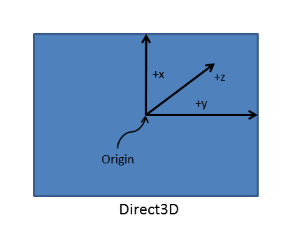
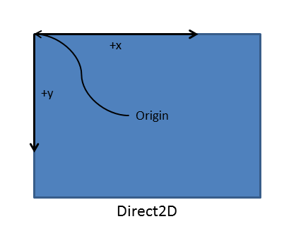
第一,兩者使用不同的笛卡兒座標模型。 Direct2D 使用右手規則,其中 Y 座標從原點向上移動、朝正值增加。 不過,Direct3D 使用左手規則,其中 Y 座標從原點向右移動、朝正值增加。 結果是螢幕座標的原點位於 Direct2D 的左上方,而螢幕的原點 (投影平面) 則位於 Direct3D 的左下方。 (如需詳細資訊,請參閱<3D 座標系統>)。
第二,3D 旋轉矩陣必須明確指定,避免四捨五入錯誤。
交換鏈結假設原點位於左下方,因此您必須執行旋轉,對齊使用右手規則的 Direct2D 座標系統,以及交換鏈結所用的左手規則座標系統。 具體來說,對於新左手方向中的影像,您可以透過下列方式來重新定位:將「旋轉矩陣」乘以「 旋轉後座標系統原點的轉移矩陣」,然後將影像從 CoreWindow 的座標空間轉換成交換鏈結的座標空間。 Direct2D 轉譯目標與交換鏈結連結時,應用程式也必須一致套用此轉換。 不過,如果應用程式正在繪製到與交換鏈結無直接關聯的中繼表面,則請勿套用此座標空間轉換。
從四種可能的旋轉方向選取正確矩陣的程式碼,看起來可能如下 (請注意新座標系統原點的轉移):
// Set the proper orientation for the swap chain, and generate 2D and
// 3D matrix transformations for rendering to the rotated swap chain.
// Note the rotation angle for the 2D and 3D transforms are different.
// This is due to the difference in coordinate spaces.  Additionally,
// the 3D matrix is specified explicitly to avoid rounding errors.

switch (displayRotation)
{
case DXGI_MODE_ROTATION_IDENTITY:
    m_orientationTransform2D = Matrix3x2F::Identity();
    m_orientationTransform3D = ScreenRotation::Rotation0;
    break;

case DXGI_MODE_ROTATION_ROTATE90:
    m_orientationTransform2D =
        Matrix3x2F::Rotation(90.0f) *
        Matrix3x2F::Translation(m_logicalSize.Height, 0.0f);
    m_orientationTransform3D = ScreenRotation::Rotation270;
    break;

case DXGI_MODE_ROTATION_ROTATE180:
    m_orientationTransform2D =
        Matrix3x2F::Rotation(180.0f) *
        Matrix3x2F::Translation(m_logicalSize.Width, m_logicalSize.Height);
    m_orientationTransform3D = ScreenRotation::Rotation180;
    break;

case DXGI_MODE_ROTATION_ROTATE270:
    m_orientationTransform2D =
        Matrix3x2F::Rotation(270.0f) *
        Matrix3x2F::Translation(0.0f, m_logicalSize.Width);
    m_orientationTransform3D = ScreenRotation::Rotation90;
    break;

default:
    throw ref new FailureException();
}
有了 2D 影像的旋轉矩陣和原點之後,在 ID2D1DeviceContext::BeginDraw 和 ID2D1DeviceContext::EndDraw 呼叫之間,呼叫 ID2D1DeviceContext::SetTransform,即可顯示該影像。
警告Direct2D 沒有轉換堆疊。 如果應用程式在繪製程式碼中也使用 ID2D1DeviceContext::SetTransform,則此矩陣需要後乘至已套用的任何其他轉換。
    ID2D1DeviceContext* context = m_deviceResources->GetD2DDeviceContext();
    Windows::Foundation::Size logicalSize = m_deviceResources->GetLogicalSize();

    context->SaveDrawingState(m_stateBlock.Get());
    context->BeginDraw();

    // Position on the bottom right corner.
    D2D1::Matrix3x2F screenTranslation = D2D1::Matrix3x2F::Translation(
        logicalSize.Width - m_textMetrics.layoutWidth,
        logicalSize.Height - m_textMetrics.height
        );

    context->SetTransform(screenTranslation * m_deviceResources->GetOrientationTransform2D());

    DX::ThrowIfFailed(
        m_textFormat->SetTextAlignment(DWRITE_TEXT_ALIGNMENT_TRAILING)
        );

    context->DrawTextLayout(
        D2D1::Point2F(0.f, 0.f),
        m_textLayout.Get(),
        m_whiteBrush.Get()
        );

    // Ignore D2DERR_RECREATE_TARGET here. This error indicates that the device
    // is lost. It will be handled during the next call to Present.
    HRESULT hr = context->EndDraw();
下次您呈現交換鏈結時,2D 影像將會旋轉以符合新的顯示方向。
附錄 B:套用螢幕旋轉矩陣 (3D)
在<調整交換鏈結的大小,並預先旋轉其內容>的範例程式碼 (以及 DXGI 交換鏈結旋轉範例) 中,我們已為每個可能的螢幕方向,定義具體的轉換矩陣。 現在,我們來看看旋轉 3D 場景的矩陣。 和之前一樣,請為 4 個可能的方向各建立一組矩陣。 為避免四捨五入錯誤而影響視覺成品效果,請在程式碼中明確宣告矩陣。
您可按照以下方式設定這些 3D 旋轉矩陣。 下列程式碼範例所示的矩陣是 0、90、180 和 270 度頂點的標準旋轉矩陣,這些頂點定義相機 3D 場景空間中的點。 計算場景的 2D 投影時,場景中每個頂點的 [x, y, z] 座標值都會乘以這個旋轉矩陣。
// 0-degree Z-rotation
static const XMFLOAT4X4 Rotation0(
    1.0f, 0.0f, 0.0f, 0.0f,
    0.0f, 1.0f, 0.0f, 0.0f,
    0.0f, 0.0f, 1.0f, 0.0f,
    0.0f, 0.0f, 0.0f, 1.0f
    );

// 90-degree Z-rotation
static const XMFLOAT4X4 Rotation90(
    0.0f, 1.0f, 0.0f, 0.0f,
    -1.0f, 0.0f, 0.0f, 0.0f,
    0.0f, 0.0f, 1.0f, 0.0f,
    0.0f, 0.0f, 0.0f, 1.0f
    );

// 180-degree Z-rotation
static const XMFLOAT4X4 Rotation180(
    -1.0f, 0.0f, 0.0f, 0.0f,
    0.0f, -1.0f, 0.0f, 0.0f,
    0.0f, 0.0f, 1.0f, 0.0f,
    0.0f, 0.0f, 0.0f, 1.0f
    );

// 270-degree Z-rotation
static const XMFLOAT4X4 Rotation270(
    0.0f, -1.0f, 0.0f, 0.0f,
    1.0f, 0.0f, 0.0f, 0.0f,
    0.0f, 0.0f, 1.0f, 0.0f,
    0.0f, 0.0f, 0.0f, 1.0f
    );
    }
您可使用 IDXGISwapChain1::SetRotation 呼叫,設定交換鏈結上的旋轉類型,如下所示:
m_swapChain->SetRotation(rotation);
現在,在您的轉譯方法中實作類似下方的程式碼:
struct ConstantBuffer // This struct is provided for illustration.
{
    // Other constant buffer matrices and data are defined here.

    float4x4 projection; // Current matrix for projection
} ;
ConstantBuffer  m_constantBufferData;          // Constant buffer resource data

// ...

// Rotate the projection matrix as it will be used to render to the rotated swap chain.
m_constantBufferData.projection = mul(m_constantBufferData.projection, m_rotationTransform3D);
現在,當您呼叫轉譯方法,其會將目前的旋轉矩陣 (由類別變數 m_orientationTransform3D 指定) 與目前的投影矩陣相乘,並將運算結果指派為轉譯器的新投影矩陣。 呈現交換鏈結,以更新後的顯示方向查看場景。
意見反應
即將登場:在 2024 年,我們將逐步淘汰 GitHub 問題作為內容的意見反應機制,並將它取代為新的意見反應系統。 如需詳細資訊,請參閱:https://aka.ms/ContentUserFeedback。
提交並檢視相關的意見反應