Multiple Diagrams per Model
Note
EF5 Onwards Only - The features, APIs, etc. discussed in this page were introduced in Entity Framework 5. If you are using an earlier version, some or all of the information does not apply.
This video and page shows how to split a model into multiple diagrams using the Entity Framework Designer (EF Designer). You might want to use this feature when your model becomes too large to view or edit.
In earlier versions of the EF Designer you could only have one diagram per the EDMX file. Starting with Visual Studio 2012, you can use the EF Designer to split your EDMX file into multiple diagrams.
Watch the video
This video shows how to split a model into multiple diagrams using the Entity Framework Designer (EF Designer). You might want to use this feature when your model becomes too large to view or edit.
Presented By: Julia Kornich
EF Designer Overview
When you create a model using the EF Designer’s Entity Data Model Wizard, an .edmx file is created and added to your solution. This file defines the shape of your entities and how they map to the database.
The EF Designer consists of the following components:
- A visual design surface for editing the model. You can create, modify, or delete entities and associations.
- A Model Browser window that provides tree views of the model. The entities and their associations are located under the [ModelName] folder. The database tables and constraints are located under the [ModelName].Store folder.
- A Mapping Details window for viewing and editing mappings. You can map entity types or associations to database tables, columns, and stored procedures.
The visual design surface window is automatically opened when the Entity Data Model Wizard finishes. If the Model Browser is not visible, right-click the main design surface and select Model Browser.
The following screenshot shows an .edmx file opened in the EF Designer. The screenshot shows the visual design surface (to the left) and the Model Browser window (to the right).
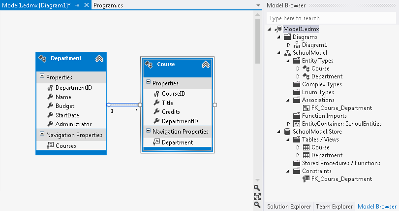
To undo an operation done in the EF Designer, click Ctrl-Z.
Working with Diagrams
By default the EF Designer creates one diagram called Diagram1. If you have a diagram with a large number of entities and associations, you will most like want to split them up logically. Starting with Visual Studio 2012, you can view your conceptual model in multiple diagrams.
As you add new diagrams, they appear under the Diagrams folder in the Model Browser window. To rename a diagram: select the diagram in the Model Browser window, click once on the name, and type the new name. You can also right-click the diagram name and select Rename.
The diagram name is displayed next to the .edmx file name, in the Visual Studio editor. For example Model1.edmx[Diagram1].

The diagrams content (shape and color of entities and associations) is stored in the .edmx.diagram file. To view this file, select Solution Explorer and unfold the .edmx file.
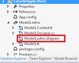
You should not edit the .edmx.diagram file manually, the content of this file maybe overwritten by the EF Designer.
Splitting Entities and Associations into a New Diagram
You can select entities on the existing diagram (hold Shift to select multiple entities). Click the right mouse button and select Move to new Diagram. The new diagram is created and the selected entities and their associations are moved to the diagram.
Alternatively, you can right-click the Diagrams folder in Model Browser and select Add new Diagram. You can then drag and drop entities from under the Entity Types folder in Model Browser onto the design surface.
You can also cut or copy entities (using Ctrl-X or Ctrl-C keys) from one diagram and paste (using Ctrl-V key) on the other. If the diagram into which you are pasting an entity already contains an entity with the same name, a new entity will be created and added to the model. For example: Diagram2 contains the Department entity. Then, you paste another Department on Diagram2. The Department1 entity is created and added to the conceptual model.
To include related entities in a diagram, rick-click the entity and select Include Related. This will make a copy of the related entities and associations in the specified diagram.
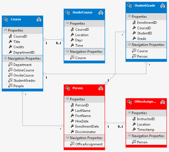
Changing the Color of Entities
In addition to splitting a model into multiple diagrams, you can also change colors of your entities.
To change the color, select an entity (or multiple entities) on the design surface. Then, click the right mouse button and select Properties. In the Properties window, select the Fill Color property. Specify the color using either a valid color name (for example, Red) or a valid RGB (for example, 255, 128, 128).
Summary
In this topic we looked at how to split a model into multiple diagrams and also how to specify a different color for an entity using the Entity Framework Designer.
Feedback
Coming soon: Throughout 2024 we will be phasing out GitHub Issues as the feedback mechanism for content and replacing it with a new feedback system. For more information see: https://aka.ms/ContentUserFeedback.
Submit and view feedback for