IOT: Using junk to build your Internet of Things thing
When I read many of the IOT articles there always seems to be the assumption that you will be able to get the items discussed in the articles. That would require a credit card, the ability to pay for shipping and so forth. After all, only Radio Shack actually carries the Arduino UNO in the US, maybe there are few of the other stores, but generally you have to online to buy electronics stuff, which requires a PayPal account, credit card and the money to pay those bills.
This blog will discuss extracting a power chip that can be used instead of power relays or power module Arduino shield. It really doesn’t have much to do with software, but rather is a basis for setting up a little test system that can test chips and put the data from the tests into the cloud for storage (but all in this blog, this is a series of blogs).
Getting started so you can replicate the articles online
Somehow, you do have to get a CPU, so the absolutely cheapest way is to buy an “Arduino” like board from TI.COM, where for $9.99 you get a 16-bit device that has a bunch of amazing technology when compared to the Arduino device with the Atmel chip that is used for the Arduino UNO. And the includes shipping. It is possible to get the devices if you attend a TeenHack in your neighborhood. The Arduino UNO can be purchased from Ebay for around $20 or less.
Once you have Arduino and created the “Blinky” app, what you do now? A motor relay board, again, will cost your around 20 to 30 dollars 2014 US, then you need motors. What about LEDs, where do get them? How about the Salvation Army, Thrift Store, etc? Yep, look for both RC controlled cars, cars with motors and so forth. CAT replicas in the US have massive power transistors in the “wired” controlled vehicles. Use a Philips screwdriver or a big hammer open up one of the vehicles and check out all of the parts. For some of these vehicles I have gotten up to 8 LEDs, two power transistor modules, 2 capacitors, 1 inductor, 2 BIG motors, 4 wheels with gears and axles. Get these separately and it will cost you around $40, so if you spend an hour breaking down the vehicle, it is just about a breakeven!
Breaking it down
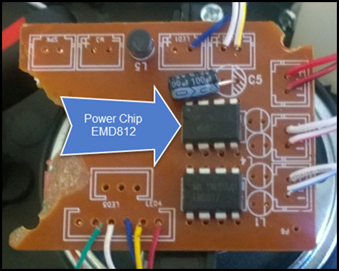
Well, if you got an Arduino UNO for Christmas or acquired one somehow, then it is likely you have an RC Controlled Car that is either broken or unused, or it might be a non-RC Controlled car or “Dancer” item your drunk uncle thought was hilarious and not sits on a shelf collecting dust. I have taken a part one of the CAT vehicles that were sort of a cross between the RC Controlled as they were wired to the controller. The CATs come with two motors usually, and either LEDs or very small incandescent bulbs (which is weird). This is handy because there are two bi-directional motor controllers, which are solid state relays and usually cost $0.63/ea in lots of less than 10, AND they are soldered as “pin-trough's” which means a very cheap soldering iron could unsolder them if you do it carefully. As you can see the board has been broken, so removing the parts and wires are a good thing to do. (We will discuss the Arduino in another article, not this one.)
Check out YouTube videos on how to do the unsoldering of the device. Usually the de-soldering braid is more useful on boards that handle motor currents as there is often a heavy copper ground “plane” or traces and the ground copper will cool the solder off before you can use a sucker de-soldering tool.
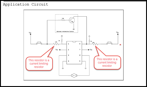
Here is a circuit you can use with your chip once you have de-soldered it. You can vary the resistance depending on what is in your junkbox, but usually if you are creating a circuit for the first time you will want to use the exact resistor shown in the application circuit. The resistor that appears to be pointing up, is connected to ground, and is a high resistance with 1,000,000 (1 M) Ohms, and although useful, will be ignored in this blog. So if you use alkaline batteries, then you would have a Vcc of 6 volts (4.8 volts if you are using 4 rechargeable). This means that the current through the resistor will be from Ohm’s Law: 6 volts/10,000 ohms= 0.0006 amps, which according to the datasheet will trigger the circuit inside of the chip to drive the motor. You DO NOT have to use the 10K resistor, you can use a lower value. Let’s check to see if 220 ohms will work, which then gives you 6 volts/220 ohms = 27 milliamps, and that is about three times to high according to the datasheet. But if you double the resistance to 440 ohms, the you will draw half the current or 13.5 milliamps, still a little high. What about a common 1,000 Ohm (1 K)? Yes, that is will work, but it will draw more current from the battery and waste it in heat. So the perfect resistor would be 600 Ohms, that would deliver to the input of the EMD812 a current of 10 milliamps, and there would be little wasted heat when used.
So now I have two EMD812, and you can find the information on this device at:
https://www.datasheet4u.com/datasheet-pdf/Elite/EMD812/pdf.php?id=720609
In reading the datasheet, it appears that the devices with an input of 10 milliamps can output up to 1 amp, which is useful for most motors that you tear out of RC control vehicles that can be purchased inexpensively from drug stores, and the like.
Other RC vehicles may use transistors, these will be either PNP or NPN or sometimes power MOSFETs (which is a type of transistor), rarely are mechanical relays used.
When you use the EMD812, it will take a great deal of abuse, but Ohm’s Law is often ignored as you one explores the world of inexpensive electronics.
Reusing wire and other parts
Wire used in the RC vehicles tends to be large gauge wire (larger gauge, smaller the wire, why? Because it is the number times the wire is drawn through the “die” or tools to get thinner, initially the wire starts at zero, 30 gauge wire is quite small.) This means that using tools like crimping tools you would use for normal wire will simply break the wire, usually it is better to solder the fine wires. To strip the wires, make sure to use a wire stripper, if you use a “hot” knife approach to striping wires, then vent your work area as some, not all of the plastics can be mildly smelly. If the wire is stranded then you might want to put a touch of solder on the leads so that the fine wires do not fray or break.
I mention this as you may not have any wire, the RC control cars tend to have lots of shorter pieces of wire, so make sure to keep the lengths as long as possible.
- Capacitors are usually a dark solid color that looks different than resistors, the actual value of the capacitors is pretty loose, but then when dealing with microprocessors are not precise, however some are polarized. The brown ones are ceramic and are not polarized usually, but check. The black, dark blue have a + symbol over one of the leads, and it is best to attach that lead to the voltage side of the circuit. These are highly reusable, motors need them, power switches, etc. to do a hardware de-bounce.
- Resistors are often a light blue or have different strips on them, de-solder these and store them.
- Inductors: Keep these, try to determine the value of the devices, if not, you can determine the value using test circuits. Important for radios.
- ICs: On radio controlled items, there may be a TX2/RX2 chip, these are the chips that rule them all. Keep them on the board for a few more blogs, these are GOLDEN and hard to buy separately in the US. They are very cheap in China though, in case you are traveling, see if you can get a bag of these in China.
Testing your circuit
Let’s say you are going to reuse these devices in other equipment you might be selling, well good! But the removal can often break things internally, either because of the heat, or when you pry the chip and pull it off the circuit board. (It is easy to stress a chip upon removal, especially plastic integrated circuit systems.) So how do you set up to test the chip? After all, if it doesn’t work and you did a bunch of work wiring it, and so forth, you would have wasted a great deal of time. The EMD812 appears to be only available in the US.
I used the datasheet link shown above and repeated here: https://www.datasheet4u.com/datasheet-pdf/Elite/EMD812/pdf.php?id=720609, there is a simple application circuit. Hardware, like software, requires that you design test circuits so that you can have some way to test incoming parts like the EMD812. I used Vcc of 9 volts, a voltage dropping resistor of 1K or 1,000 ohms to pin 1 only, I basically just set up to test one side of the chip. Why? For me it was too “expensive” to implement both sides of the symmetrical chip, for no good reason. But the not very good reasons are stated thus:
Cheaper to only use one resistor, as well as time. Assumption was made that the substrate that holds the transistors are interconnected. I may implement the other side when I add the Arduino test system I will demonstrate in another blog.
Voltage dropping the 1K Ohm resistor instead of the 10K in the schematic, the input current appears that it can vary widely, and the output will handle up to a 1 Amp current. S A F E T Y !!! The output of this device could be lethal if not managed correctly, so PLEASE be careful when working with electricity, even if it is battery powered.
How does this relate to Microsoft?
In one my future blogs I will demonstrate how to use an Arduino or equivalent to drive the test of this circuit. Another blog will cover how the output from the chip under test would then be shared with others through Azure and then another blog will show you how to use Office365 to store and present data to teammates. This is the first blog on how to break and then make new stuff from Junk.

