Deploying SDN on One single physical host using VMM - Initial Setup and Network Controller
Introduction
This topic helps you evaluate the Software Defined Networking (SDN) features available with Windows Server 2016. In particular, it focuses on using Virtual Machine Manager (VMM) 2016 to deploy Software Defined Networking on a single physical host; It includes several SDN capabilities in Windows Server 2016 such as Network Controller, Software Load-balancer and etc.
Review the following information to help understand what is SDN, plan your SDN infrastructure and deployment.
- Software Defined Networking (SDN)
- Plan a Software Defined Network Infrastructure.
- Deploy a Software Defined Network infrastructure using VMM
Prerequisites
To deploy SDN on a single physical host, you will need followings –
- A Physical machine with Dual-Socket: 8 - 16 Physical Cores, 128G RAM, 175GB local disk, 300GB HD for VM storage (can be on File Server)
- Windows Server 2016 Data Center with 9D Update
- SQL Server 2014
- Windows Assessment and Deployment Kit
- SCVMM 2016
- SCVMM Templates for SDN Deployment
Before you begin deployment, you must plan and configure your hosts and physical network infrastructure. You can get more information from Plan a Software Defined Network Infrastructure
Prepare the Physical Host
The physical host will be used as the Hyper-V Host. All you need do is to install Windows 2016 and enable Hyper-V. After Hyper-V role is enabled, create three virtual switches on the host from Hyper-V Manager UI or following PowerShell –

Make VHD of Windows Server 2016 DC with 9D Update for SDN infrastructure VMs.
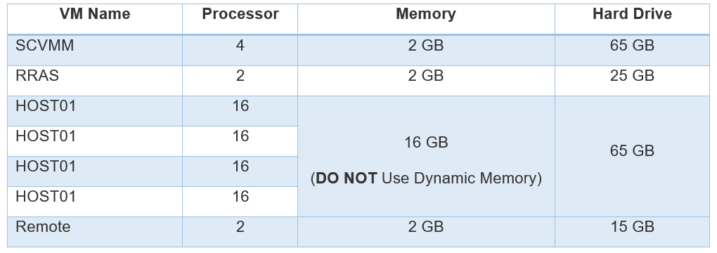
Create 7 VMs with the following names – SCVMM, RRAS, Remote, HOST01, HOST02, HOST03 and HOST04 based on the Windows Server 2016 DC with 9D VHD.
Topology view from the physical Host - 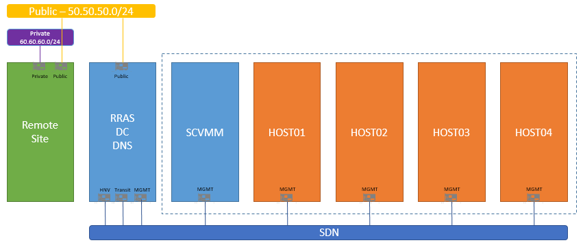
Connect these 7 VMs to the Virtual Switches as the following –
- Remote: Public, Private
- RRAS: 3 VNIC connect to SDN, one NIC connects to Public
- SCVMM, HOST01, HOST02, HOST03 and HOST04: SDN
Name VNICs of SCVMM with following names – MGMT, HNV, Transit, Public
Give VLAN ID of SCVMM VNICs – 7 for MGMT, 10 for Transit and 11 for HNV
Enable trunk mode on NIC of Host01 to Host04 to allow Vlan 7, 10 and 11, you can find more information - https://technet.microsoft.com/en-us/library/hh848475.aspx
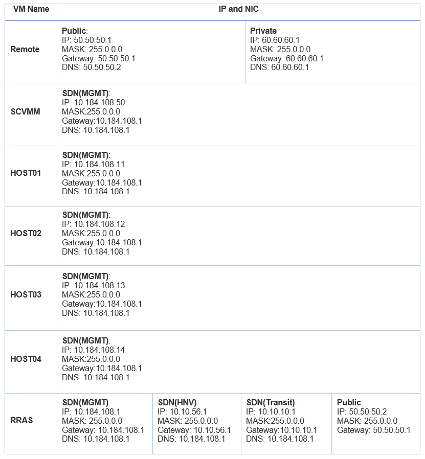
Manually Setup Static IPs to these 7 VMs on their VNICs –
Enable Nested Virtualization on HOST01 to HOST04 by PowerShell. You can find more information for running nested virtualization in Hyper-V from - https://msdn.microsoft.com/en-us/virtualization/hyperv_on_windows/user_guide/nesting 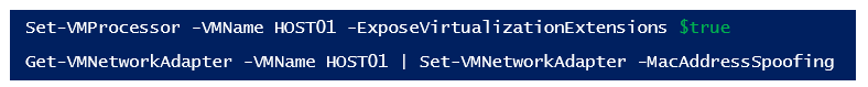
Prepare the VMs
Start all the VMs 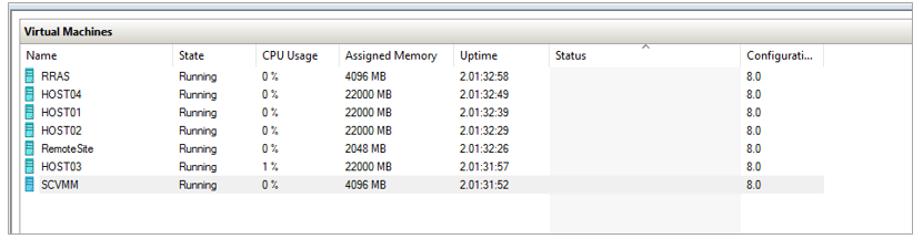
RRAS VM
- Rename computer name as “RRAS”
- Install “Active Directory Domain Services” Role and configure the RRAS server as the DC. Create a root domain – “SDN.LAB”
- Install “DNS Server” role, and configure the DNS
- Install “Remote Access” Role
- Create an Active Directory security group for network controller management - SDNMGMT
You need to create an Active Directory security group for network controller management. The group should be a Domain Local group. Members of this group will be able to create, delete, and update the deployed network controller configuration. You need to create at least one user account that is a member of this group and have access to its credentials. - Create an Active Directory security group for network controller clients - SDNCLIENT
You need to create an Active Directory security group for network controller clients. The group should be a Domain Local group. Once the network controller is deployed, any members of this group will have permissions to communicate with the network controller via REST based interface. You need to create at least one user account that is a member of this group. After the network controller is deployed, VMM can be configured to use this user's account credentials to establish communication with the network controller.
HOST01 – HOST04 VMs
- Rename computer Name as “HOST01 – HOST04”
- Join VMs to the SDN.LAB domain.
- Enable Hyper-V role on the VM, do not use Hyper-V to create VSwitch based on the VNIC.
SCVMM VM
- Rename computer Name as “SCVMM”
- Join VM to the SDN.LAB domain.
- Install .Net Framework V3.5 feature from Server Manager
- Install Windows Assessment and deployment kit (ADK)j
- Install SQL Server 2014
- Install SCVMM
Remote VM
- Rename VM Name as “Remote”
- Install Remote Access role
- Install IIS, change the default page of the default website to something meaningful, such as the HTML page with the content can show the page is on the remote host.
Deploy the SDN
Plan SDN
This experiment environment is intentionally to align with the SDN topology as Plan a Software Defined Network Infrastructure, except we are using the single node Network Controller and without NICs teaming due to the performance of the nested virtualization environment.
The topology of the SDN is as the following -
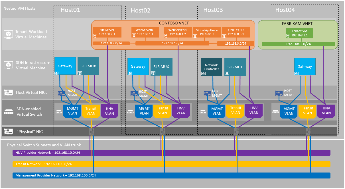
- MGMT – Management network routes off-cloud to other management subnets
- Transit Network routes off-cloud to external client subnets
- HVN Provider network only routes to other HNV Provider subnets in the cloud.
Network topology – 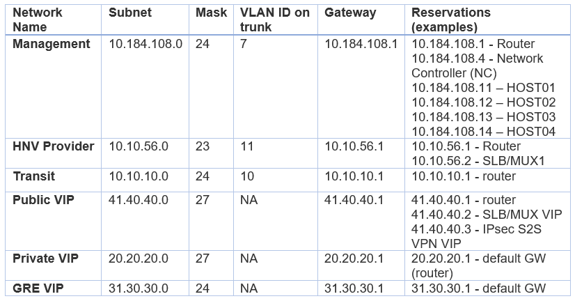
MUX ASN – 64628, Gateway ASN: 65000, LOCAL ASN on Remote VM: 64623
Deploy Network Controller
Prepare an SSL self-signed Certificate
You need an SSL certificate that will be used to establish secure communication (https) between VMM and the network controller. We will generate a self-signed certificate for the deployment.
Run the following PowerShell on the SCVMM VM:

Export the certificate
After requesting the certificate, use the Certificates snap-in (certlm.msc) to export it (located in Personal/Certificates) and its private key into a .pfx file. When exporting, choose Personal Information Exchange - PKCS #12 (.PFX) and accept the default to Include all certificates in the certification path if possible. The export wizard requires that you protect the private key by either a security or a password. Be sure to assign a password, as you will need it later during network controller deployment.
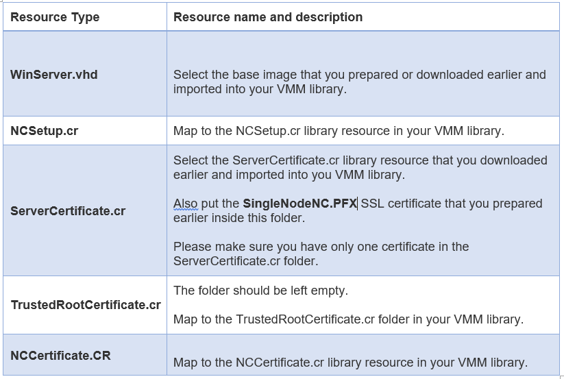
Later, this “SingleNodeNC .PFX” certificate should be placed directly in the ServerCertificate.cr folder for use during deployment. Details of ServerCertificate.cr folder are included in following sections in this guide.
Import the service template include template VHD
Copy all the templates you download from GitHub - Microsoft SDN GitHub repository to the folder –
C:\Programdata\Virtual Machine Manager Library Files\
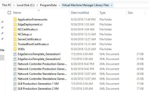
Copy Windows Server 2016 + 8D sysprep VHD to the C:\Programdata\Virtual Machine Manager Library Files\VHDS 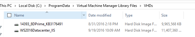
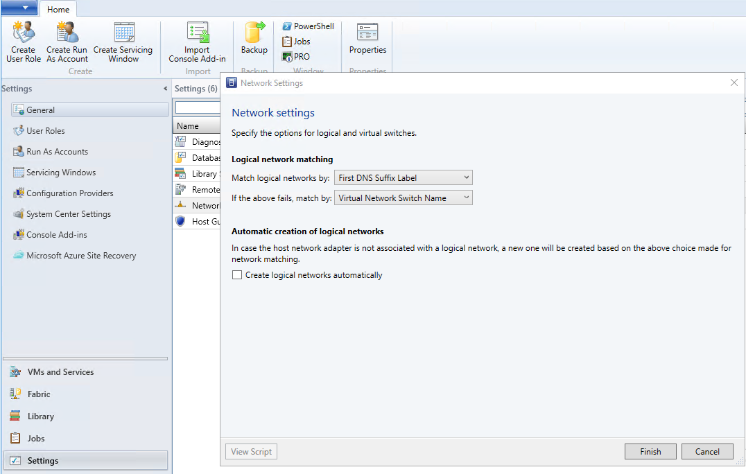
Setup Network Settings in SCVMM
Open SCVMM Console, and go to Settings -> Network Settings, Uncheck “Create logical networks automatically” and Press “Finish"
Add HOST01 – HOST04 to SCVMM
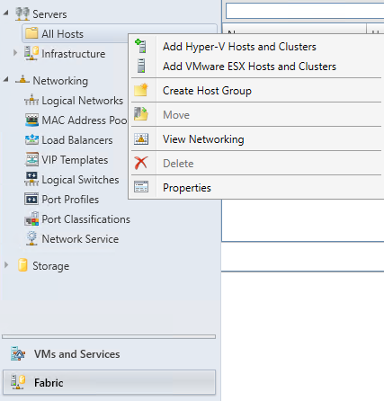
- Open VMM Console, click “Fabric” and click on the “Servers > All Hosts”.
- Right click the “All Hosts” and select “Add Hyper-V Hosts and Clusters”
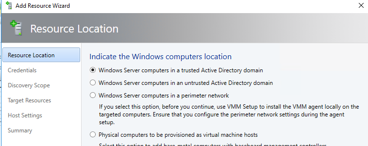
3. Select “Windows Server computer in a trusted Active Directory domain”.
4. In the Credentials page, select user an existing Run As Account, click on Browse and click on “Create Run As Account” to create a “Run_As” account – SDN\Administrator 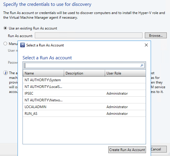
5. Type “HOST” in the “Computer names” text field then press next to search the hosts
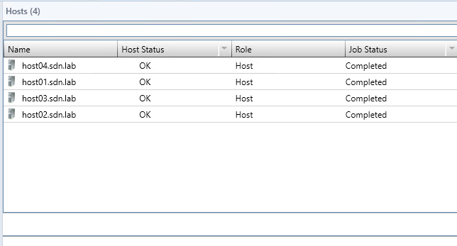
6. You will see host01 to host04 displayed on the “Target Resources” page, Click the button “Select All”, then click “Next”.
7. Click Next
8. On Summary page confirm the settings and click “Finish”.
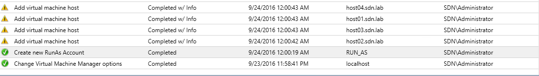
9. All 4 hosts will be added to the “All Host” group when the jobs are completed as the following.
Create the Management logical network
Now you can create the Management logical network and the Management logical switch.
The Management logical network models the Management network connectivity for the VMM host, network controller hosts, and tenant virtual machine hosts. It's recommended that you create this Management network specifically to provide connectivity to network controller managed infrastructure virtual machines.
- Open the Fabric workspace in the VMM Console, expand Networking and select the Logical Networks
- Right-click the Logical Network node and select Create Logical Network.
- Specify “MGMT” as the name and optional Description for this network. Click Next.
- On the Settings page, be sure to select One Connected Network, since all Management networks need to have routing and connectivity between all hosts in that network. Check the Create a VM Network with the same name to automatically create a VM Network for your Management network. Click Next.
- In the Network Site panel, click Add to add a new network site. Select the host group for the hosts that will be managed by the network controller. Insert your management network IP subnet information. This network should already exist and be configured in your physical switch. Click Next when you are ready to proceed.
- Review the Summary information and click Finish to complete.
For a highly available network controller deployment, you need a REST IP address that can be assigned to the network controller service. This REST IP address will be reserved from the Management logical network IP address space. So now create an IP address pool for the Management logical network and reserve an IP address for the network controller service.
Create the IP Address pool in the Management logical network:
- Right-click the Management logical network in VMM and select Create IP Pool from the drop down menu.
- Provide a name and optional description for the IP Pool and ensure that the Management network is selected for the logical network. Click Next.
- On the Network Site panel, select the subnet that this IP address pool will service. Click Next.
- On the IP Address range panel, type the starting and ending IP addresses.
Important
Don't use the first three IP addresses of your available subnet. For example, if your available subnet is from .1 to .254, start your range at .4 or greater.
In IP addresses to be reserved for other uses, type one of the IP addresses from the specified range. This is the IP address that you will later use as the REST IP of the network controller Service. Click Next. - Next, configure the default gateway address.
- Optionally configure DNS information.
- Optionally configure WINS server information, but this is generally not required. Click Next.
- Review the summary information and click Finish to complete the wizard.
Create a Management logical switch
The Management logical switch needs to be deployed on the network controller host(s) and provides the Management network connectivity to the network controller virtual machines.
- Click Create Logical Switch on the ribbon in the VMM Console.
- Review the Getting Started information and click Next.
- Provide a “MGMT-LSWITCH” as the name and optional Description. For the Uplink mode, be sure to select No Uplink Team. Click Next.
- For Minimum Bandwidth mode, choose the default option. Click Next.
- Uncheck all the switch extensions in the Extensions This is a crucial step as selecting any of the switch extensions at this stage may block network controller on-boarding later.

6. You can add a Virtual Port Profile and choose a Port Classification for Host Management on this page if you want but it is not required. Click Next when you're finished.
7. Create a new Uplink Port Profile directly from the Logical Switch wizard. Click Add and select New Uplink Port Profile from the drop down menu.
8. Provide a name and optional description for your uplink port profile.
- Use the defaults for Load Balancing algorithm and Teaming Mode.
- Make sure you select all the network sites that are part of the Management logical network you created. Leave the Load Balancing Algorithm as Host Default, and Teaming Mode as Switch Independent.
- Select the Uplink Port Profile you created and click New virtual network adapter. This adds a host virtual network adapter (vNIC) to your logical switch and uplink port profile, so when you add the logical switch to your hosts, the vNICs get added automatically.
- Provide a name for the vNIC. Verify that the Management VM network is listed under the Connectivity
- Select This network adapter will be used for host management and then select Inherit connection settings from the host adapter. This allows you to take the vNIC adapter settings from the adapter that already exists on the host.
- If you created a port classification and virtual port profile earlier, you can select it now.
- Click Next.
- Review the Summary information and click Finish to complete the wizard.
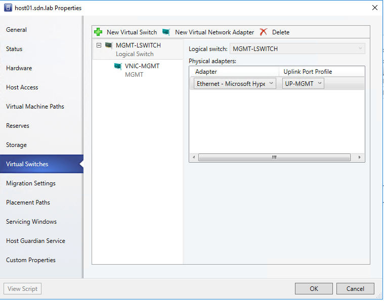
Applying a logical switch on HOST01-HOST04 by
- Click VMs and Services
- Right click on HOST machine under “All Hosts” group
- Click on “Virtual Switches” on the left and click on “New Virtual Switch” then Choose the Logical Switch you just created
- Click on New Virtual Network Adapter to also create a VNIC
Import the service template into the VMM library
- In VMM, navigate to Library.
- In the top of the left pane, in the Templates section, select Service Templates.
- In the ribbon at the top, click Import Template.
- Browse to your service template folder, select the Network Controller Standalone Generation 2 VM.xml file and follow the prompts to import it.
- The service template uses the following virtual machine configuration parameters. Update the parameters for your environment as you import the service template.
Configure and deploy the service
Use the following procedure to deploy a network controller service instance:
- Select the network controller service template and click Configure Deployment to begin. You must type a Service name “NCService” and select a destination for the service instance. The destination must map to a Host Group that contains Windows Server RTM hosts and that is going to be managed by network controller.
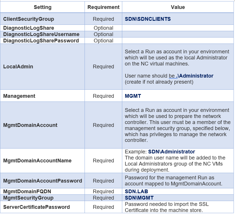
- On the left side of the Configure Deployment window, there are several settings that you must configure. The table below summarizes each field's values.
It is normal for the virtual machine instances to be initially red. Click Refresh Preview to have the deployment service automatically find suitable hosts for the virtual machines to be created.
Input Network controller Name as “SingleNodeNC”
After you configure these settings, click Deploy Service to begin the service deployment job. Deployment times will vary depending on your hardware but are typically between 30 and 60 minutes.
Add Network Service wizard
- Navigate to the Fabric Node in the VMM console.
- Right-click the Network Service icon under Networking and click Add Network Service.
- The Add Network Service Wizard Click Next.
- Input “NCService” as your network controller Network Service name. Then Click Next.
- Select Microsoft for the manufacturer and for model select Microsoft network controller. Click Next.
- On the Credentials tab, provide the RunAs account you want to use to configure the Network Service. This should be the same account that you included in the network controller Clients group. Click Next
SERVERURL=https://SingleNodeNC.SDN.LAB;servicename=NCService - On the Review Certificates page, a connection is made to the network controller virtual machine to retrieve the certificate. Verify that the certificate shown is the one you expect. Ensure you select the These certificates have been reviewed and can be imported to the trusted certificate storebox check box. Click Next.
- On the next screen, click Scan Provider to connect to your service and list the properties and their status. This is also a good test of whether or not the service was created correctly, and that you"re using the right connect string to connect to it. Examine the results, and ensure that the property isNetworkController = true is set. When it completes successfully click Next.
- Configure the Host Group in VMM that your network controller will manage. Click Next.
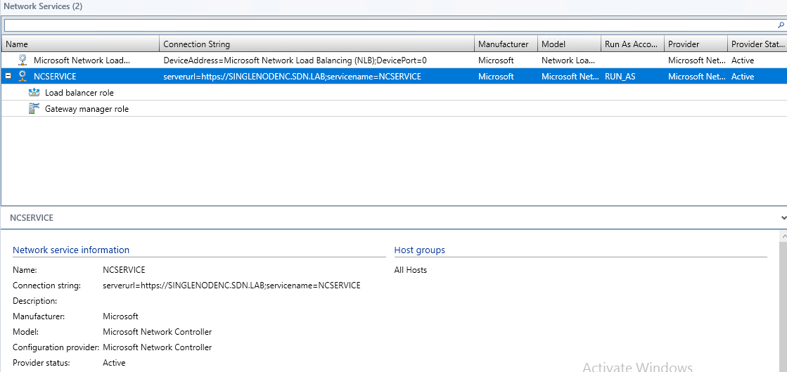
- Click Finish to complete the Add Network Service Wizard. When the service has been added to VMM, you should see it appear in the Network Services list in the VMM Console, and it should look similar to the following:
In case the add Network Service operation fails, please check the job logs in VMM UI for diagnostics and take recommended remedial steps before retrying.
Create the HNV Provider network for tenant VM connectivity
The network controller is connected to the Management network, which is the network used to deploy and manage the network controller through VMM. Next, you need to create the HNV Provider network that is managed by the network controller in your SDN fabric. This network is used to validate that the network controller has been deployed successfully and that tenant virtual machines within same virtual network can ping each other.
To create HNV Provider logical network
- Start the Create Logical Network Wizard.
- Type a “HNV” as the name and optional description for this network. Click Next.
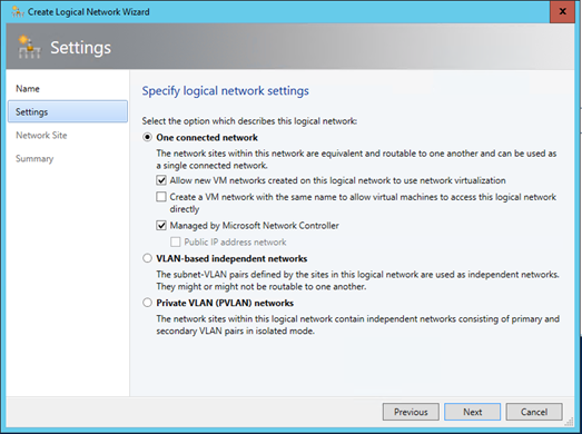
- On the Settings page, verify that One Connected Network is selected, since all HNV Provider networks need to have routing and connectivity between all hosts in that network. Ensure you check Allow new VM networks created on this logical network to use network virtualization. You will also see a new setting: Managed by the network controller. Ensure you check this box, and then click Next.
4. On the Network Site panel, add the network site information for your HNV Provider network. This should include the Host Group, Subnet and VLAN information for your HNV Provider network. Remember, this network should already exist in your physical network devices and all your SDN fabric hosts should have physical connectivity to it
5. Review the Summary information and complete the wizard.
Create the HNV Provider logical network IP address pool
VMM requires that the HNV Provider logical network has an IP address pool, even if DHCP is available on this network. So, you need to create a static IP address pool that is associated with this logical network.
To create an IP address pool in HNV Provider logical network
- Right-click the HNV Provider logical network in VMM and select Create IP Pool from the drop down menu.
- Provide a name and optional description for the IP Pool and ensure that the HNV Provider logical network is selected for the logical network. Click Next.
- On the Network Site panel, you need to select the subnet that this IP address pool will service. If you have more than one subnet as part of your HNV Provider network, you need to create a static IP address pool for each subnet. If you have only one site (for example, like the sample topology) then you can just click Next.
- On the IP Address range panel, configure the starting and ending IP address. Click Next
Important
Don't use the first three IP addresses of your available subnet. For example, if your available subnet is from .1 to .254, start your range at .4 or greater. - Next, configure the default gateway address. Click Insert next to the Default gateways box, type the address and use the default metric. Click Next.
- Optionally configure DNS information, but this is generally not required.
- Optionally configure WINS server information, but this is generally not required. Click Next.
- Review the summary information and click Finish to complete the wizard.
- As part of network controller on-boarding, the switch that you deployed on the hosts for the Management logical network connectivity was converted to an SDN switch. This switch can now be used to deploy a network controller managed network including the HNV Provider logical network. Ensure you select the network site corresponding to the HNV Provider logical network in the uplink port profile settings for the Management logical switch.
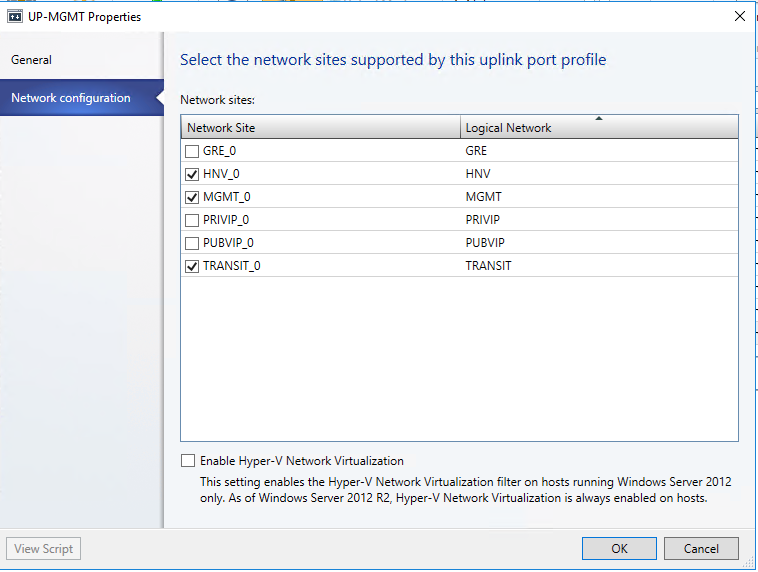
10. Make sure HNV_0 and MGMT_0 are both checked.
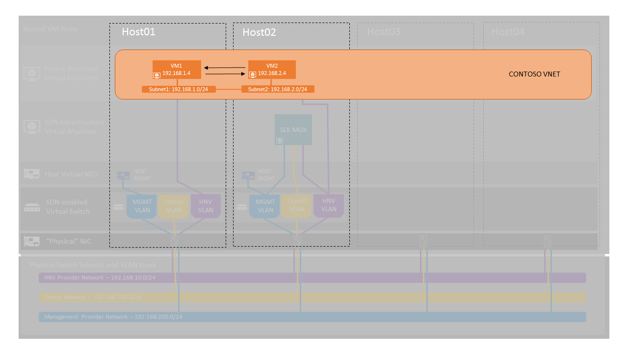
Validation by finishing following exercise Exercise Description: Create a Tenant Virtual Network and VMs
In this exercise, you will be creating your own tenant virtual network and connecting two VMs to it using System Center Virtual Machine Manager (SCVMM).
The image below gives a high-level view of the topology we will be creating in this exercise.
Tasks
- Open System Center Virtual Machine Manager (SCVMM) Console
Double-click the Virtual Machine Manager Console icon on the Desktop
Leave default login settings as-is with Server name: localhost:8100|
Click “Connect” - Open the VM Networks and IP Pools Pane
Click on “VMs and Services” in the bottom-left hand side of the console
Click on “VM Networks” in the “VMs and Services” Pane
Click “VM Networks” in the Ribbon menu - Open Create VM Network Wizard
Click “Create VM Network” in Ribbon menu - Configure VM Network Name and Description
Input “CONTOSO” as the name for the virtual network you are creating
Optionally, provide a description for the virtual network
Make sure Logical network is set to HNV
Click “Next” - Select Isolation
Leave the default radio button selection; “Isolate using Hyper-V network virtualization”
Leave the default IP address protocol for both the VM and logical network as IPv4
Click “Next” - Create VM Subnets
Click “Add” button
Enter a “Subnet1” as the name for the first VM Subnet
Enter the subnet (IP Prefix) – 192.168.1.0/24 – for the first VM subnet.
You need to make sure to use 192.168.1.0/24 as your first subnet.
Click “Add” button again
Enter a name for the second VM Subnet (E.g. “Subnet2”)
Enter a subnet for the second VM subnet (E.g. 192.168.2.0/24)
Click “Next” - Skip Connectivity Section
We will not be providing external connectivity for this virtual network through a VPN tunnel, direct routing, or NAT in this exercise.
Click “Next” - Create VM Network
Click the View Script button to see the SCVMM PowerShell script used to create this network
Click “Finish” - Create an IP Pool
Right-click the Virtual Network you just created and select “Create IP Pool" - 10.Specify the IP Address Pool Name and VM Subnet
Note: You will be creating a separate IP Pool for each VM Subnet
Input “Pool1” in the Pool name and optionally provide a description
Ensure the VM Network listed is the VM Network you just created
Select the first “Subnet1” you created
Click “Next” - Specify an IP Address Range
No action is necessary on this page. Click Next.
Leave the Starting and Ending IP addresses as the default
There is no need to reserve an IP addresses for VIPs or other use - Specify a Gateway
No action is necessary on this page. Click Next.
The lowest IP address in the subnet is the default gateway – this will be chosen automatically if field is left blank. - Skip Specify a DNS server
Click “Next” - Skip Specify a WINS server
Click “Next” - Create First VM Subnet’s IP Pool
Click “Finish” to confirm settings and create the IP Pool - Create Second VM Subnet’s IP Pool
Input “Pool2” as the second pool name
Repeat steps 9 – 15, for your second VM Subnet - Subnet2 - Create a Virtual Machine
Click “All Hosts” in the “VMs and Services” pane on the left-hand side of the screen
Click “VMs” icon in the Ribbon menu
Click, “Create Virtual Machine” and select “Create Virtual Machine” from the Ribbon menu - Select the source for the new Virtual Machine
Use the default option “Use an existing virtual machine, …” and click “Browse”
Navigate down to the sys-prep Windows Server 2016 VHD you copied to the SCVMM template library in “VHDX TYPE” section and click it, then select “OK”
Click “Next” - Specify Virtual Machine Identity
Input “VM1” as the name for the virtual machine and optionally enter a description.
Make sure “Generation 2” is selected.
Please leave “Turn on shielding support in the virtual machine after deploying it” unchecked.
Click “Next” - Configure Hardware
Under “Compatibility,” click the “Hyper-V” profile
Under “General” in the left menu pane, select “Processor” and ensure “number of processors” is set to 2.
Maintain default settings of 2 processors and 2048 MB of memory
Under “Network Adapters,” select “Network Adapter 1”
On the right-hand side of the window under “Connectivity,” select “Connected to a VM network”.
Browse to the “CONTOSO” VM Network you previously created –
Select a VM Subnet attached to the “Subnet1” subnet you previously created
Click “Next” - Place the virtual machine on a host
Click “Next” to skip “Select Destination” step.
Choose the first recommended host on which to deploy this virtual machine
Particularly if you are completing this step for the second time (after reaching step 26 of this exercise), feel free to select a different Hyper-V host – assuming it is recommended with three or more stars - to spread out the VM deployments.
Click “Next” - Skip Configure Settings
Click “Next” - Skip Add Properties Section
Select the “Start the virtual machine after deploying it” checkbox.
Click “Next” - Confirm Settings and Deploy VM
Select the “Start the virtual machine after deploying it” checkbox
Click “Create”
It will take a few minutes to create the virtual machine. Check the Jobs pane to see when deployment is complete. - Create another Virtual Machine
Repeat Steps 17 – 25 above with a different VM Name “VM2” and different Subnet “Subnet2”
For this exercise, please do not create more than two VMs as physical memory and CPU is limited - Open a console session to the VMs
Check the Virtual Machine State for your VMs. If the status says “Stopped”, then right click on the VM, and click “Power On”.
Check the Status of your VMs. After the status of each of your Virtual Machines has changed to “Running” (as opposed to “Creating…”), select “VMs and Services” in the bottom-left hand side of the VMM console
Click on “All Hosts” in the “VMs and Services” pane
Click on “VMs” in the Ribbon menu
Right-click any one of the VMs you just deployed and select “Connect or View” => “Connect via Console”
Login with password, you setup for the VMs - Validate Virtual Network Connectivity in each of your created VMs
Upon logging in, you may see a Networks pane on the right side. Click on “No”, although it does not matter what you pick.
Right-click the Windows Icon in the Start Menu and click on a “Command prompt (Admin)”.
Type “ipconfig” and press “Enter”
Record the IP Address of the VM.
Open a Console Session in another VM (open console using instructions in Step 26) and open its command prompt.
Ping the first VM from the second VM (or vice-versa). You should receive several replies. - Config Firewall policy on both VM1 and VM2 to allow them to Ping each other.
Run- New-NetFirewallRule -DisplayName “Allow ICMPv4-In” -Protocal ICMPv4 - Login VM1 one, open CMD to ping VM2 IP to see if it works.
- Congratulations! You just attached two of your VMs on different subnets to a virtual network. And they can route between each other. In a larger organization, you can create separate virtual networks for different apps and tenants, and they will be completely isolated from each other.