Creating a simple Windows 10 IoT application - LED Dice
 By Paul Winstanley, Microsoft System Center Configuration Manager Consultant, SCCM Solutions Ltd. He has 20 years experience in IT and is a community contributor to Windows Management User Group (WMUG) and blogs at sccmentor.wordpress.com.
If you want to kick start some development in the world of Windows 10 IoT it can be a daunting place to start. You'll need to get yourself up and running with the Windows 10 O/S on your Raspberry Pi 2 and also have Visual Studio 2015 installed on your PC. Microsoft has a great guide on how to do this.
Once you have everything configured then what next?
The following tutorial shows you how to set up a basic Windows 10 LED Dice, a simple application to turn on some lights, learn some C# along the way and to help out anyone starting out with this O/S. The basic idea is that you can click a button to roll the die and the result is displayed on screen. The corresponding number of LED lights will then light up on the breadboard.
What You Need
The following components are needed for this tutorial:
- A Raspberry Pi 2 running Windows 10 IoT Core
- Visual Studio 2015 (Community Edition is free)
- 7 Male to Female jumper wires
- 6 x LED lights (any colour)
- 6 x Resistors (I've used 270 Ω)
- A breadboard (I've used a half size breadboard)
Setting up Visual Studio
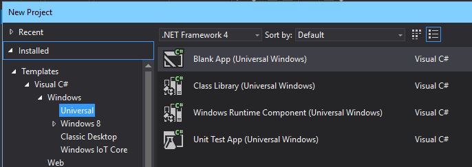
You will need to create a new project in Visual Studio and import the Windows 10 IoT references. To do this select File>New>Project.
Choose a Windows\Universal Blank App and name the project appropriately.
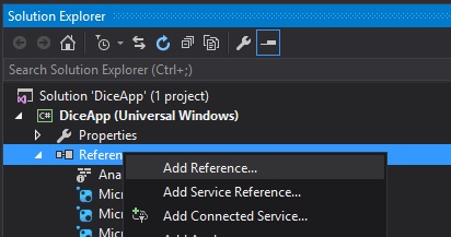
In Solution Explorer right click the References and choose Add Reference
Add in the Windows 10 IoT reference under Universal Windows>Extensions. Click Ok. 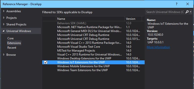
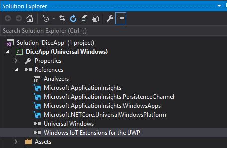
The reference will be added.
What exactly is a reference? Well MSDN states the following - 'Before you write code against an external component or connected service, your project must first contain a reference to it. A reference is essentially an entry in a project file that contains the information that Visual Studio needs to locate the component or the service.' So for the Raspberry Pi project you'll need to add the reference so you can use the GPIO pin components and control them.
Create the IoT Interface
Before delving into the code behind the app you'll need to create a simple GUI interface so you can roll the dice. To do this in Solution Explorer right click MainPage.xaml and choose 'View Designer' 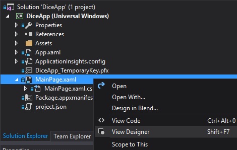
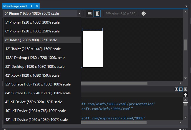
This will open up the Designer view in the main body of Visual Studio. You'll have a choice of device type to design your interface for - I'm going to select 8" tablet.
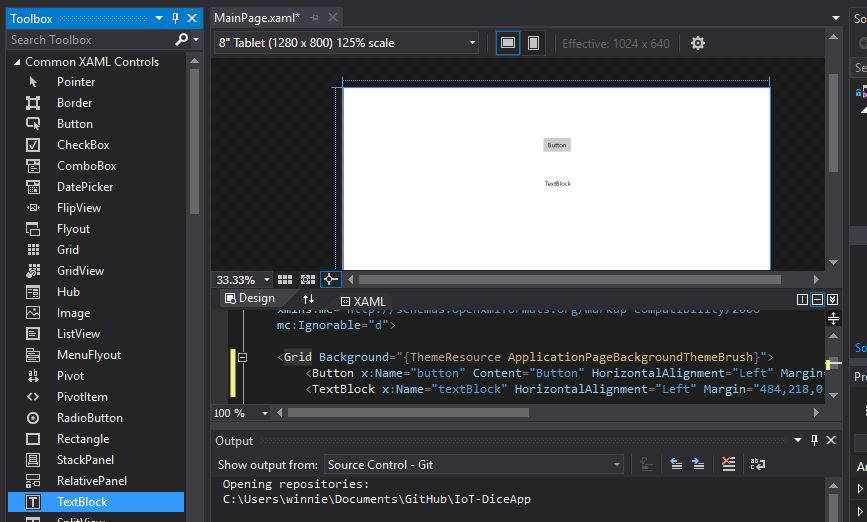
You can zoom into the view to then start adding in elements to the design. For the IoT dice interface you will need to add in a button to roll the dice and a text box to display the results of the roll. If you do not have a Toolbox window in your Visual Studio then click the View menu and choose Toolbox.
From the Toolbox drag a button and textbox across to the design window and add as below:
Now that you have a button in your interface you need to define what your button will do. For the IoT dice, if you click the button it needs to display a response in the text box i.e. it will display the result of the dice roll. To do this you need to create an event handler for the button.
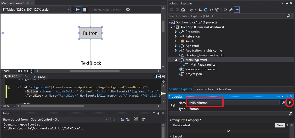
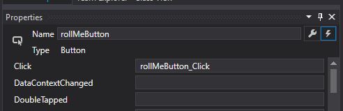
First, give the button a meaningful name. Highlight the button in the Designer view and enter a name in Properties - I have called my button 'rollMeButton'. Next click the event handler icon.
Enter some relevant details in the Click section of the event handler. I have named it 'rollMeButton_Click'
This will create a block of code in the file MainPage.xaml.cs. The content of this code will determine what happens when the button is clicked. The code generated is as below:
private void rollMeButton_Click(object sender, RoutedEventArgs e) { }
Now it's time to give the button and the textbox some labels so they mean something to the end user.
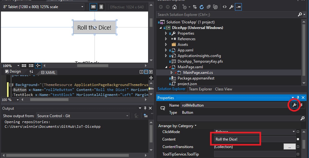
Click the settings icon in the button's properties and in the Content field enter 'Roll the Dice! ' You'll notice that the label updates in the Designer view window to reflect the change you have made.
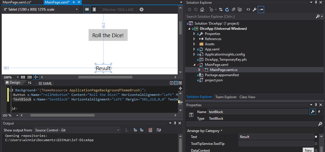
For the Textbox highlight it and enter 'Result' in the Text field.
Apart from adding an element for GPIO that's the basics behind our user interface. Next we need to start building the code to roll the dice and turn on some LED lights.
Building the code
So far we've been setting up the interface in Designer View and this has been making changes to the file MainPage.xaml. The associated .cs file - MainPage.xaml.cs - is where we will perform all the coding logic behind the Dice application.
What exactly do we want to achieve with our code? Here are the basic steps I want to achieve from the project:
- Initialise the GPIO pins, set them to turned off and put them in output mode.
- Roll the dice
- Turn off the LED lights
- Generate a random number between one and six
- Wait in a turned off state for a duration of 1 second
- Turn on a number of LED lights that match the generated random number
- Repeat steps 2 - 6
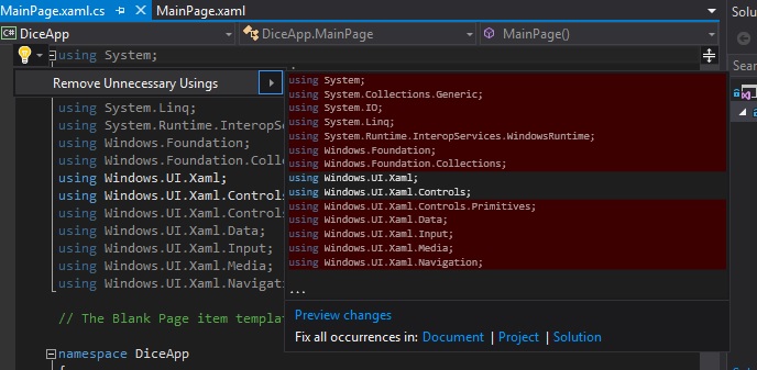
Let's start by cleaning up unnecessary code. At the top of the code click into the using Directive section. Notice the light bulb appear. Click the drop down next to it and choose 'Remove Unnecessary Usings' . You'll notice the unnecessary code is highlighted for removal. Go ahead and do this.
To be able to use the GPIO pins we need to add in the Windows.Devices.Gpio namespace with the command 'using Windows.Devices.Gpio;' 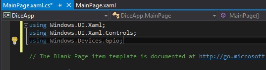
Note that the light bulb reappears and if you click it you'll be prompted to remove the unnecessary usings. That is because we haven't entered name code from that nameplace. We'll rectify this as we build up the code.
In the 'public sealed partial class MainPage : Page' section of code we are going to declare all the variables we need for the project. We need to set the which GPIO pins to use, give them a name, declare a timer and also somewhere to store the result of the dice throw.
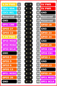
We can refer to a GPIO pin diagram to determine which pins to use and the GPIO value of the pins. Take a look at the image below, for the Dice app we are going to use GPIO 26, 13, 6, 5, 22 & 27. We'll see how they relate to the pins on the Raspberry Pi later.
Insert the following code:
private const int ONELED_PIN = 26; private const int TWOLED_PIN = 13; private const int THREELED_PIN = 6; private const int FOURLED_PIN = 5; private const int FIVELED_PIN = 22; private const int SIXLED_PIN = 27; private GpioPin onepin; private GpioPin twopin; private GpioPin threepin; private GpioPin fourpin; private GpioPin fivepin; private GpioPin sixpin; private int LEDResult = 0; private DispatcherTimer timer; 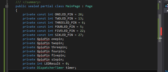
Now that we have declared our variables we need to initialise the GPIO pins. By default GPIO pins are set to input so we need to set their mode to ouput.
In the section 'public MainPage()' enter 'InitGPIO();' 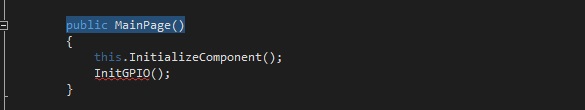
Next create a private void called InitGPIO(). The code below is required in this method.
private void InitGPIO() { var gpio = GpioController.GetDefault();
// Show an error if there is no GPIO controller
if (gpio == null)
{
onepin = null;
twopin = null;
threepin = null;
fourpin = null;
fivepin = null;
sixpin = null;
GpioStatus.Text = "There is no GPIO controller on this device.";
return;
}
onepin = gpio.OpenPin(ONELED_PIN);
twopin = gpio.OpenPin(TWOLED_PIN);
threepin = gpio.OpenPin(THREELED_PIN);
fourpin = gpio.OpenPin(FOURLED_PIN);
fivepin = gpio.OpenPin(FIVELED_PIN);
sixpin = gpio.OpenPin(SIXLED_PIN);
//Turn off all LEDs and set to GPIO pins to output
onepin.Write(GpioPinValue.Low);
onepin.SetDriveMode(GpioPinDriveMode.Output);
twopin.Write(GpioPinValue.Low);
twopin.SetDriveMode(GpioPinDriveMode.Output);
threepin.Write(GpioPinValue.Low);
threepin.SetDriveMode(GpioPinDriveMode.Output);
fourpin.Write(GpioPinValue.Low);
fourpin.SetDriveMode(GpioPinDriveMode.Output);
fivepin.Write(GpioPinValue.Low);
fivepin.SetDriveMode(GpioPinDriveMode.Output);
sixpin.Write(GpioPinValue.Low);
sixpin.SetDriveMode(GpioPinDriveMode.Output);
}
What exactly does the above code do? First it checks for the existence of a GPIO controller on the device. If one doesn't exist then "There is no GPIO controller on this device" will be returned. Next it sets our GPIO pins to equal the integer value declared earlier - so onepin will equal 26, twopin will equal 13 etc. Finally the pins are set to GPIOPinValue.Low, which means they are turned off and DriveMode is set to output. Referring back to the seven steps needed for our Dice app, we have just achieved Step 1.
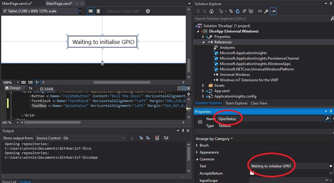
You may notice that GpioStatus.Text is underlined and showing an error. We need to create a text box in our Interface to display this error should a GPIO controller not exist on our end device - i.e. Raspberry Pi.

To do this click the MainPage.xaml window and add a textbox to your Interface. In the textbox properties enter 'GpioStatus' for the name and add 'Waiting to initialise GPIO' in the text field
Before we proceed with the main section of code that handles Steps 2-7 of our objective we need to add in some code that determines what happens to the pins should we close the application down. If you take a look at the GpioPin class at MSDN, then we need to take advantage of the Dispose Method and release the pins.
Add the following to your code:
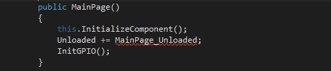
In the public MainPage() section add the line 'Unloaded += MainPage_Unloaded;'
Your code in this section should now look like this:
Create a private void called 'MainPage_Unloaded'
Enter the code: private void MainPage_Unloaded(object sender, object args) { // Cleanup onepin.Dispose(); twopin.Dispose(); threepin.Dispose(); fourpin.Dispose(); fivepin.Dispose(); sixpin.Dispose(); }
Now that we have handled the Dispose Method we can focus on completing the code to roll the dice and light the LED lights. Here's a reminder of the steps we need to code.
- Roll the dice
- Turn off the LED lights
- Generate a random number between one and six
- Wait in a turned off state for a duration of 1 second
- Turn on a number of LED lights that match the generated random number
- Repeat steps 2 - 6
We previously created a 'Roll the dice!' button and when we added an event handler for a click called ' rollMeButton_Click' this created some code for us. In this block of code we need to enter what will happen if we roll the dice. From our steps above we are going to enter Steps 3 - 5 in this block of code. Step 2 is handled by the button's click event.
Step 3 - Turn off the LED lights - why would we do this? This step is added to reset the state of the LED's if the dice has already been thrown. We need to turn them off and also create a pause of one second before switching them back on (Step 5). The pause is added to avoid the lights coming back on immediately. If the same number is rolled you will not notice this change in state between on and off .
To turn off the lights we can re-use the code specified earlier to set the pin write mode to Low. // Turn off all LEDs between throws onepin.Write(GpioPinValue.Low); twopin.Write(GpioPinValue.Low); threepin.Write(GpioPinValue.Low); fourpin.Write(GpioPinValue.Low); fivepin.Write(GpioPinValue.Low); sixpin.Write(GpioPinValue.Low);
Step 4 - Generate a random number between one and six
//Generate a random number for the roll of the dice Random random = new Random(); int randomNumber = random.Next(1, 7); LEDResult = randomNumber; string randomResult = randomNumber.ToString(); textBlock.Text = randomResult;
Let's break down the code above to see what is happening.
The first two lines utilise the Random class and will generate a random number between one and six and store the result as an integer in the variable 'randomNumber' . A variable LEDResult is made equal to 'randomNumber' and 'randomNumber' is converted to a string value and stored in the variable 'randomResult' . Finally the variable 'randomResult' is displayed on screen in the 'Result' textbox that we created earlier.
A bit confusing but basically the integer LEDResult will be used to store the result of the dice throw and light the relevant number of LED lights whilst randomResult will be used to output the result to the screen in our Results text box.
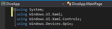
You'll notice that some of the code is underlined in red, this is because we need to enter 'using System;' in the Directive section at the start of our code.
Step 5 - Wait in a turned off state for a duration of 1 second
//Start timer for 1 second to keep LEDs turned off timer = new DispatcherTimer(); timer.Interval = TimeSpan.FromMilliseconds(1000); timer.Tick += Timer_Tick; timer.Start();
The above code creates a timer and set the timer's interval to 1000 milliseconds or 1 second. The timer then calls a portion of code called Timer_Tick. Notice if you enter this code Timer_Tick is underlined, as before this is because we haven't defined the code yet. We need to define what happens after the interval. So we move onto Step 6 - Turn on a number of LED lights that match the generated random number as this is what we want to happen after the one second pause.
Step 6 - Turn on a number of LED lights that match the generated random number
private void Timer_Tick(object sender, object e) { timer.Stop();
//Output the dice roll to the LEDs
if (LEDResult == 1)
{
// Turn on 1 LED
onepin.Write(GpioPinValue.High);
}
else if
(LEDResult == 2)
{
// Turn on 2 LEDs
onepin.Write(GpioPinValue.High);
twopin.Write(GpioPinValue.High);
}
else if
(LEDResult == 3)
{
// Turn on 3 LEDs
onepin.Write(GpioPinValue.High);
twopin.Write(GpioPinValue.High);
threepin.Write(GpioPinValue.High);
}
else if
(LEDResult == 4)
{
// Turn on 4 LEDs
onepin.Write(GpioPinValue.High);
twopin.Write(GpioPinValue.High);
threepin.Write(GpioPinValue.High);
fourpin.Write(GpioPinValue.High);
}
else if
(LEDResult == 5)
{
// Turn on 5 LEDs
onepin.Write(GpioPinValue.High);
twopin.Write(GpioPinValue.High);
threepin.Write(GpioPinValue.High);
fourpin.Write(GpioPinValue.High);
fivepin.Write(GpioPinValue.High);
}
else if
(LEDResult == 6)
{
// Turn on 6 LEDs
onepin.Write(GpioPinValue.High);
twopin.Write(GpioPinValue.High);
threepin.Write(GpioPinValue.High);
fourpin.Write(GpioPinValue.High);
fivepin.Write(GpioPinValue.High);
sixpin.Write(GpioPinValue.High);
}
}
This code initially stops the timer interval and then starts a simple if>else statement. If our LEDResult variable, the result of the dice throw, is equal to one, then set one of the GPIO outputs to high and therefore light a LED; else if LEDResult is equal to two then set the output of two GPIO pins to high and so on until we reach a LEDResult of six.
You can download all the code from GitHub.
Building out the circuit
Now that we have our DiceApp code in place we need to build the electric circuit to handle the lighting of the LED lights. We can prototype the design of the circuit using Fritzing, which is an excellent open source tool that allows you to document your prototypes.
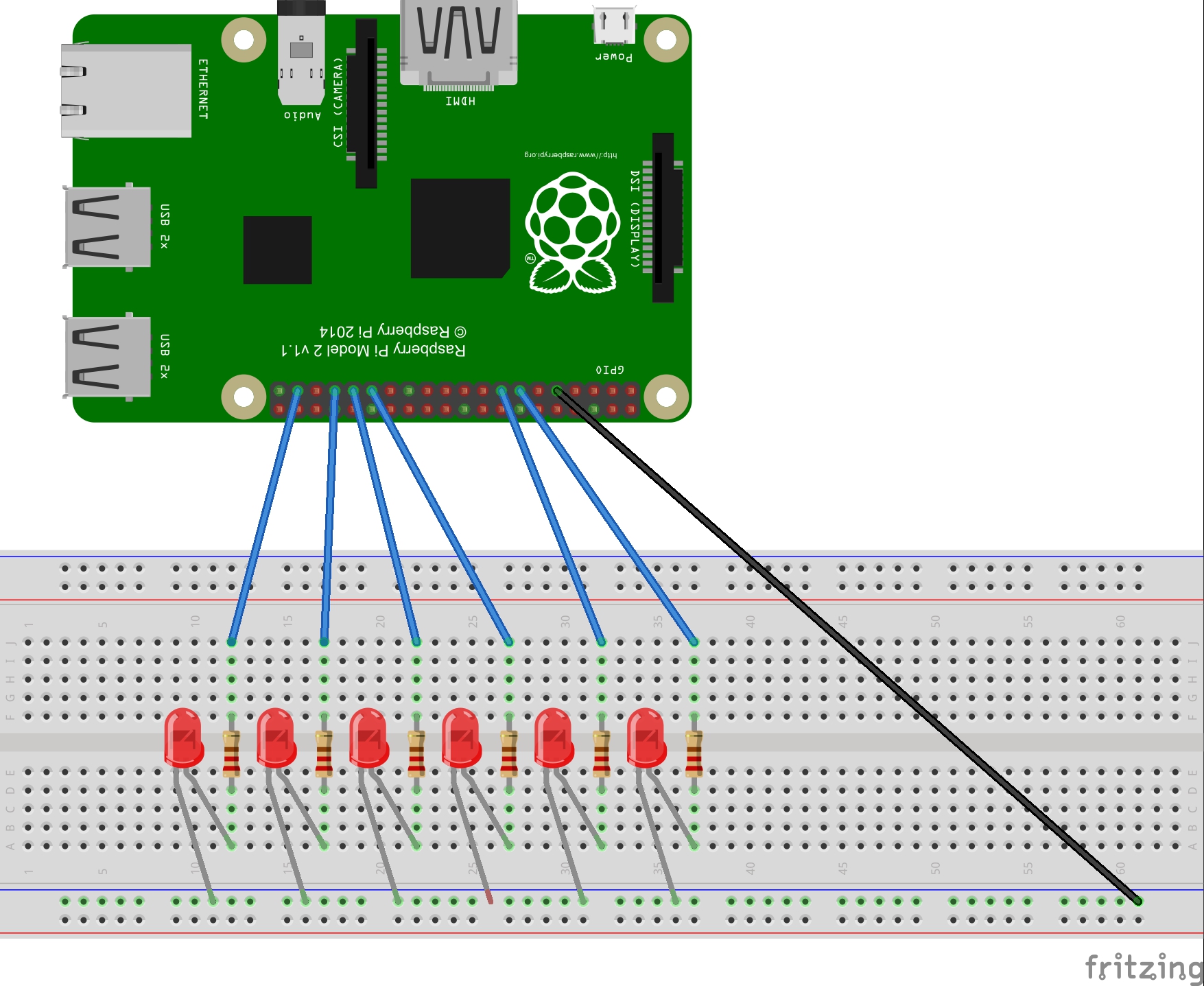
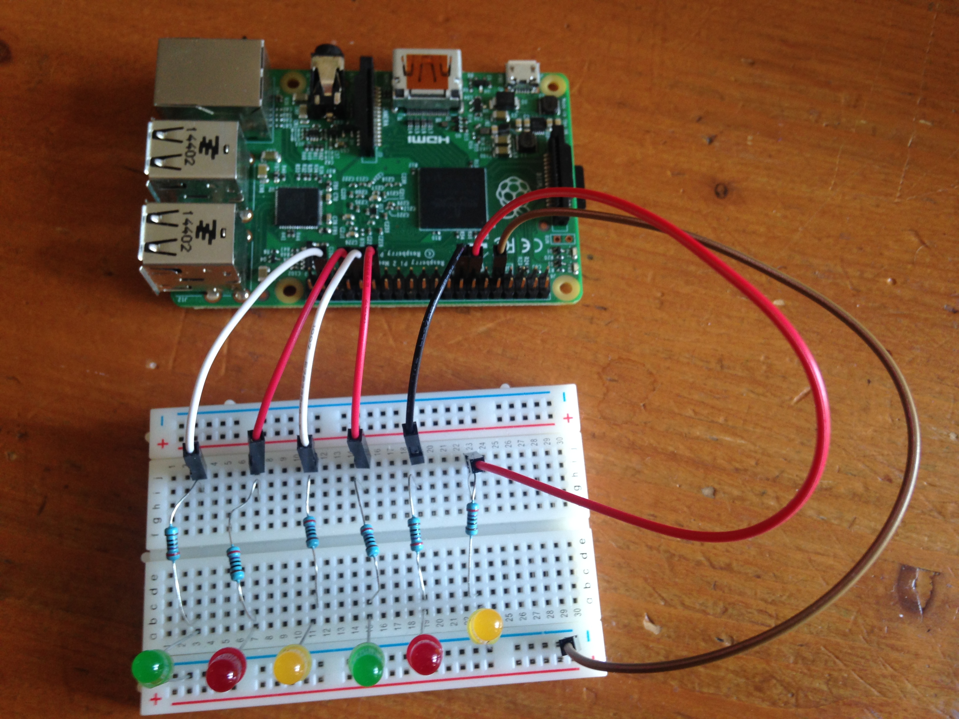
If you refer to the GPIO pin diagram earlier and the pin number defined in the code you can see that the blue wires plugged into the GPIO pins on the Pi relate. Each blue wire connects on the breadboard and a resistor is placed in front of the LED for each wire. If a resistor is not added to the circuit then the power output from the pins would blow the LED light.
The negative end of the LED (the short leg of the LED) is connected to the resistor end of the circuit and the positive end of the LED is placed along the same row as the ground (black wire). The ground is connected to pin 9 (GND - again check the GPIO pin diagram), although it can be connected to any pin that is defined as ground (e.g. pin 6).
Here's how this looks once built out.
Upload and Run
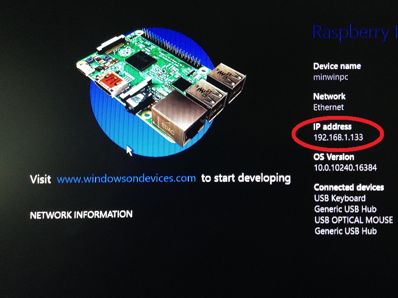
With the circuit now built we need to run the code within Visual Studio. This will upload to the Pi and report back if there are any errors in the code. So power up the Windows 10 IoT O/S and take a note of the IP address displayed on the screen.
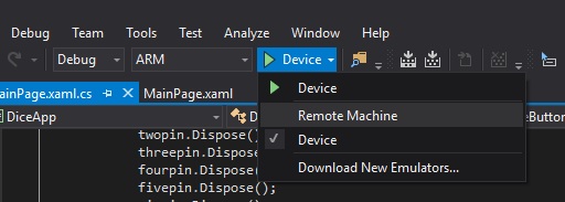
Now in Visual Studio choose Debug & ARM from the drop down menus. Then click the Device drop down and choose Remote Machine.
In the Remote Machine window enter the IP address of your Raspberry Pi and choose 'None' for authentication. Click Select.
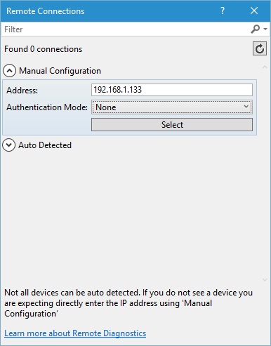
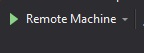
Back on the main screen click the Remote Machine button to upload the code to the Pi.
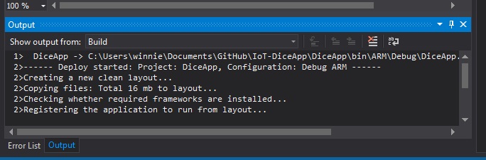
Visual Studio will output information on the upload any failures that will need to be address.
When successfully uploaded you'll be presented with your DiceApp Interface on your monitor. Press the Roll the Dice! button to roll your dice and the resultant number of LED lights will be lit on your breadboard. Here's the DiceApp in action.
`
`
There you go. A simple but operational Windows 10 IoT Dice Application.
This blog post is dedicated to my father, who would have been amazed to find his son tinkering with electric circuits and resistors after struggling to understand all the concepts as a child.