Remote monitoring preconfigured solution walkthrough
The IoT Suite remote monitoring preconfigured solution is an implementation of an end-to-end monitoring solution for multiple machines running in remote locations. The solution combines key Azure services to provide a generic implementation of the business scenario. You can use the solution as a starting point for your own implementation and customize it to meet your own specific business requirements.
This article walks you through some of the key elements of the remote monitoring solution to enable you to understand how it works. This knowledge helps you to:
- Troubleshoot issues in the solution.
- Plan how to customize to the solution to meet your own specific requirements.
- Design your own IoT solution that uses Azure services.
Logical architecture
The following diagram outlines the logical components of the preconfigured solution:
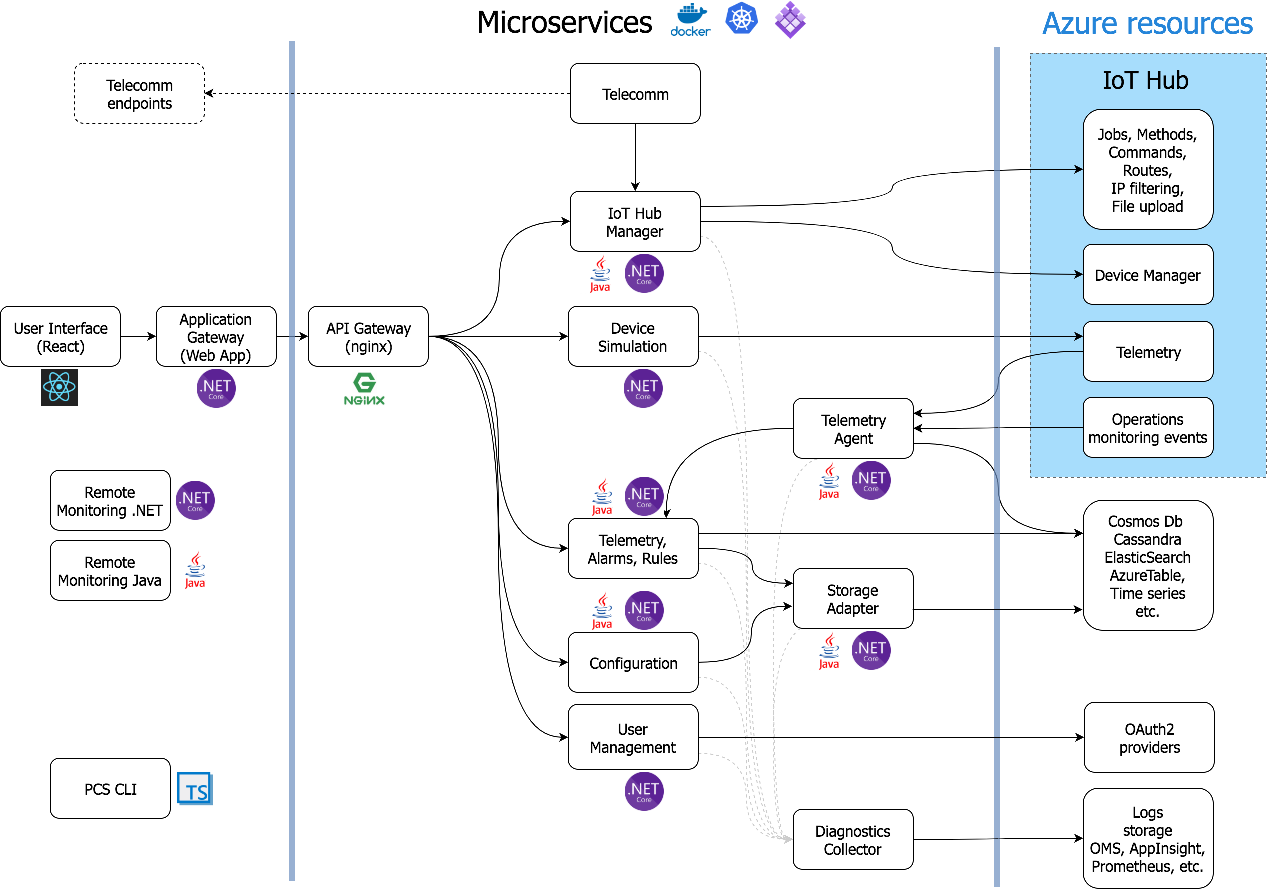
Microservices & Docker Containers
Remote Monitoring is the first of our preconfigured solutions to leverage a microservices architecture. The solution is available in both .NET and Java. Microservices have emerged as a prevalent pattern to achieve scale and flexibility (by allowing containers to be scaled individually), without compromising development speed. Microservices compartmentalize the code and provide well defined interfaces making the solution easier to understand and less monolithic. It also further expands options for partners that want to extend our current solution accelerators to build finished solutions that can be monetized.
Learn more about Docker Containers
Simulated devices
In the preconfigured solution, the simulated device represents a cooling device (such as a building air conditioner or facility air handling unit). When you deploy the preconfigured solution, you also automatically provision four simulated devices that run in an Azure WebJob. The simulated devices make it easy for you to explore the behavior of the solution without the need to deploy any physical devices. To deploy a real physical device, see the Connect your device to the remote monitoring preconfigured solution tutorial.
Device-to-cloud messages
Each simulated device can send the following message types to IoT Hub:
| Message | Description |
|---|---|
| Startup | When the device starts, it sends a device-info message containing information about itself to the back end. This data includes the device id and a list of the commands and methods the device supports. |
| Presence | A device periodically sends a presence message to report whether the device can sense the presence of a sensor. |
| Telemetry | A device periodically sends a telemetry message that reports simulated values for the temperature and humidity collected from the device's simulated sensors. |
Note
The solution stores the list of commands supported by the device in a Cosmos DB database and not in the device twin.
Properties and device twins
The simulated devices send the following device properties to the twin in the IoT hub as reported properties. The device sends reported properties at startup and in response to a Change Device State command or method.
| Property | Purpose |
|---|---|
| Config.TelemetryInterval | Frequency (seconds) the device sends telemetry |
| Config.TemperatureMeanValue | Specifies the mean value for the simulated temperature telemetry |
| Device.DeviceID | Id that is either provided or assigned when a device is created in the solution |
| Device.DeviceState | State reported by the device |
| Device.CreatedTime | Time the device was created in the solution |
| Device.StartupTime | Time the device was started |
| Device.LastDesiredPropertyChange | The version number of the last desired property change |
| Device.Location.Latitude | Latitude location of the device |
| Device.Location.Longitude | Longitude location of the device |
| System.Manufacturer | Device manufacturer |
| System.ModelNumber | Model number of the device |
| System.SerialNumber | Serial number of the device |
| System.FirmwareVersion | Current version of firmware on the device |
| System.Platform | Platform architecture of the device |
| System.Processor | Processor running the device |
| System.InstalledRAM | Amount of RAM installed on the device |
The simulator seeds these properties in simulated devices with sample values. Each time the simulator initializes a simulated device, the device reports the pre-defined metadata to IoT Hub as reported properties. Reported properties can only be updated by the device. To change a reported property, you set a desired property in solution portal. It is the responsibility of the device to:
- Periodically retrieve desired properties from the IoT hub.
- Update its configuration with the desired property value.
- Send the new value back to the hub as a reported property.
From the solution dashboard, you can use desired properties to set properties on a device by using the device twin. Typically, a device reads a desired property value from the hub to update its internal state and report the change back as a reported property.
Note
The simulated device code only uses the Desired.Config.TemperatureMeanValue and Desired.Config.TelemetryInterval desired properties to update the reported properties sent back to IoT Hub. All other desired property change requests are ignored in the simulated device.
Methods
The simulated devices can handle the following methods (direct methods) invoked from the solution portal through the IoT hub:
| Method | Description |
|---|---|
| InitiateFirmwareUpdate | Instructs the device to perform a firmware update |
| Reboot | Instructs the device to reboot |
| FactoryReset | Instructs the device to perform a factory reset |
Some methods use reported properties to report on progress. For example, the InitiateFirmwareUpdate method simulates running the update asynchronously on the device. The method returns immediately on the device, while the asynchronous task continues to send status updates back to the solution dashboard using reported properties.
Commands
The simulated devices can handle the following commands (cloud-to-device messages) sent from the solution portal through the IoT hub:
| Command | Description |
|---|---|
| PingDevice | Sends a ping to the device to check it is alive |
| StartTelemetry | Starts the device sending telemetry |
| StopTelemetry | Stops the device from sending telemetry |
| ChangeSetPointTemp | Changes the set point value around which the random data is generated |
| DiagnosticTelemetry | Triggers the device simulator to send an additional telemetry value (externalTemp) |
| ChangeDeviceState | Changes an extended state property for the device and sends the device info message from the device |
Note
For a comparison of these commands (cloud-to-device messages) and methods (direct methods), see Cloud-to-device communications guidance.
IoT Hub
The IoT hub ingests data sent from the devices into the cloud and makes it available to the Azure Stream Analytics (ASA) jobs. Each stream ASA job uses a separate IoT Hub consumer group to read the stream of messages from your devices.
The IoT hub in the solution also:
- Maintains an identity registry that stores the ids and authentication keys of all the devices permitted to connect to the portal. You can enable and disable devices through the identity registry.
- Sends commands to your devices on behalf of the solution portal.
- Invokes methods on your devices on behalf of the solution portal.
- Maintains device twins for all registered devices. A device twin stores the property values reported by a device. A device twin also stores desired properties, set in the solution portal, for the device to retrieve when it next connects.
- Schedules jobs to set properties for multiple devices or invoke methods on multiple devices.
Azure Stream Analytics
In the remote monitoring solution, Azure Stream Analytics (ASA) dispatches device messages received by the IoT hub to other back-end components for processing or storage. Different ASA jobs perform specific functions based on the content of the messages.
Job 1: Device Info filters device information messages from the incoming message stream and sends them to an Event Hub endpoint. A device sends device information messages at startup and in response to a SendDeviceInfo command. This job uses the following query definition to identify device-info messages:
SELECT * FROM DeviceDataStream Partition By PartitionId WHERE ObjectType = 'DeviceInfo'
This job sends its output to an Event Hub for further processing.
Job 2: Rules evaluates incoming temperature and humidity telemetry values against per-device thresholds. Threshold values are set in the rules editor available in the solution portal. Each device/value pair is stored by timestamp in a blob which Stream Analytics reads in as Reference Data. The job compares any non-empty value against the set threshold for the device. If it exceeds the '>' condition, the job outputs an alarm event that indicates that the threshold is exceeded and provides the device, value, and timestamp values. This job uses the following query definition to identify telemetry messages that should trigger an alarm:
WITH AlarmsData AS
(
SELECT
     Stream.IoTHub.ConnectionDeviceId AS DeviceId,
     'Temperature' as ReadingType,
     Stream.Temperature as Reading,
     Ref.Temperature as Threshold,
     Ref.TemperatureRuleOutput as RuleOutput,
     Stream.EventEnqueuedUtcTime AS [Time]
FROM IoTTelemetryStream Stream
JOIN DeviceRulesBlob Ref ON Stream.IoTHub.ConnectionDeviceId = Ref.DeviceID
WHERE
     Ref.Temperature IS NOT null AND Stream.Temperature > Ref.Temperature

UNION ALL

SELECT
     Stream.IoTHub.ConnectionDeviceId AS DeviceId,
     'Humidity' as ReadingType,
     Stream.Humidity as Reading,
     Ref.Humidity as Threshold,
     Ref.HumidityRuleOutput as RuleOutput,
     Stream.EventEnqueuedUtcTime AS [Time]
FROM IoTTelemetryStream Stream
JOIN DeviceRulesBlob Ref ON Stream.IoTHub.ConnectionDeviceId = Ref.DeviceID
WHERE
     Ref.Humidity IS NOT null AND Stream.Humidity > Ref.Humidity
)

SELECT *
INTO DeviceRulesMonitoring
FROM AlarmsData

SELECT *
INTO DeviceRulesHub
FROM AlarmsData
The job sends its output to an Event Hub for further processing and saves details of each alert to blob storage from where the solution portal can read the alert information.
Job 3: Telemetry operates on the incoming device telemetry stream in two ways. The first sends all telemetry messages from the devices to persistent blob storage for long-term storage. The second computes average, minimum, and maximum humidity values over a five-minute sliding window and sends this data to blob storage. The solution portal reads the telemetry data from blob storage to populate the charts. This job uses the following query definition:
WITH
    [StreamData]
AS (
    SELECT
        *
    FROM [IoTHubStream]
    WHERE
        [ObjectType] IS NULL -- Filter out device info and command responses
)

SELECT
    IoTHub.ConnectionDeviceId AS DeviceId,
    Temperature,
    Humidity,
    ExternalTemperature,
    EventProcessedUtcTime,
    PartitionId,
    EventEnqueuedUtcTime,
    *
INTO
    [Telemetry]
FROM
    [StreamData]

SELECT
    IoTHub.ConnectionDeviceId AS DeviceId,
    AVG (Humidity) AS [AverageHumidity],
    MIN(Humidity) AS [MinimumHumidity],
    MAX(Humidity) AS [MaxHumidity],
    5.0 AS TimeframeMinutes
INTO
    [TelemetrySummary]
FROM [StreamData]
WHERE
    [Humidity] IS NOT NULL
GROUP BY
    IoTHub.ConnectionDeviceId,
    SlidingWindow (mi, 5)
Event Hubs
The device info and rules ASA jobs output their data to Event Hubs to reliably forward on to the Event Processor running in the WebJob.
Azure storage
The solution uses Azure blob storage to persist all the raw and summarized telemetry data from the devices in the solution. The portal reads the telemetry data from blob storage to populate the charts. To display alerts, the solution portal reads the data from blob storage that records when telemetry values exceeded the configured threshold values. The solution also uses blob storage to record the threshold values you set in the solution portal.
WebJobs
In addition to hosting the device simulators, the WebJobs in the solution also host the Event Processor running in an Azure WebJob that handles command responses. It uses command response messages to update the device command history (stored in the Cosmos DB database).
Cosmos DB
The solution uses a Cosmos DB database to store information about the devices connected to the solution. This information includes the history of commands sent to devices from the solution portal and of methods invoked from the solution portal.
Solution portal
The solution portal is a web app deployed as part of the preconfigured solution. The key pages in the solution portal are the dashboard and the device list.
Dashboard
This page in the web app uses PowerBI javascript controls (See PowerBI-visuals repo) to visualize the telemetry data from the devices. The solution uses the ASA telemetry job to write the telemetry data to blob storage.
Device list
From this page in the solution portal you can:
- Provision a new device. This action sets the unique device id and generates the authentication key. It writes information about the device to both the IoT Hub identity registry and the solution-specific Cosmos DB database.
- Manage device properties. This action includes viewing existing properties and updating with new properties.
- Send commands to a device.
- View the command history for a device.
- Enable and disable devices.
Next steps
The following TechNet blog posts provide more detail about the remote monitoring preconfigured solution:
- IoT Suite - Under The Hood - Remote Monitoring
- IoT Suite - Remote Monitoring - Adding Live and Simulated Devices
You can continue getting started with IoT Suite by reading the following articles: