Overview
.jpg)
New Aircraft Procedures
This document describes some helpful procedures when using the modeling tools to create a new aircraft model for ESP. It is not a tutorial, and it is recommended that this document be read in full before starting on a new aircraft project. A high level of expertise with 3ds max is assumed and required.
See Also
- Animation Tags
- Library Objects
- Modeling Materials
- SDK Overview
- Texturing Aircraft Models
- Using Modeling Tools
Table of Contents
Getting Started on a New Aircraft
Setting Units of Measurement
Importing 3 View Drawings
Aircraft Center Point
Friendly Names and Guids
The Exterior Model
Exterior Model Hierarchies
Triangle Counts
Specific Material Settings for Aircraft
- General Material
- Propeller
- Glass
- Chrome
- Skinned Meshes
- Tail Number
- LOD_5
Texture Naming
Animation System
Tagging
Untagging
Visibility Tags
Adding Lights
Adding Doors and Exits
Adding Pilots
The Interior Model
Interior Model Hierarchies
Virtual Cockpit Specific Materials
- Windshield
- Gauges
Interior Animation Tagging
Mouse Rectangle Tags
Updating the Panel Configuration File
Getting Started on a New Aircraft
- Setting Units of Measurement
- Importing 3 View Drawings
- Aircraft Center Point
- Friendly Names and Guids
Ensure that the required setup process has been completed, and that 3ds max is running with the Aces Tools entry on the main menu. The setup process is described in the Using Modeling Tools document.
Note
This document was prepared using 3ds max 7, so there may be minor differences to the commands if you are using 3ds max 8.
Setting Units of measurement
- On the Customize menu, click Units Setup.
- In the Units Setup dialog box, click Metric, select Meters from the Metric box, and then click OK.
- On the Customize menu, click Preferences. On the General tab under System Unit Scale, verify that it reads 1 Unit = 1.0 Meters, and then click OK.
Importing 3 View Drawings
It is good practice to work through 3 View drawings. These should be separated into front, top and side images and loaded into the corresponding view ports through Views>Viewport Background>Background Source>Files.

Select Match Bitmap and turn off Lock Zoom/Pan.
Create a geometrical plane with the dimensions of the aircraft corresponding to the view chosen.
Zoom in the plane to match the 3 view drawing. Once the size of the plane and drawing match, check the Lock Zoom/Pan box. This locks the drawing with the aspect of the plane and allows you to zoom in and out of both. Do this for all of the three views (front, left and top).
Aircraft Center Point
In the DC3 model example, we use a dummy as the top object in the hierarchy. We place this object at 0,0,0 in the model. This location also refers to the quarter co-ordinate point on the aircraft also known as the aircraft center. The green box in the image below is the center point of the aircraft.
.jpg) |
Friendly Names and Guids
Aircraft models require a friendly name and guid which is authored with the ExportLOD tool.
Select Aces Tools>LODandGuid. In the Get and Set the GUID and Friendly Name section select Create new GUID for this file.
The Friendly Name info dialog box will appear. Enter a name in the box and press the Go! Button.
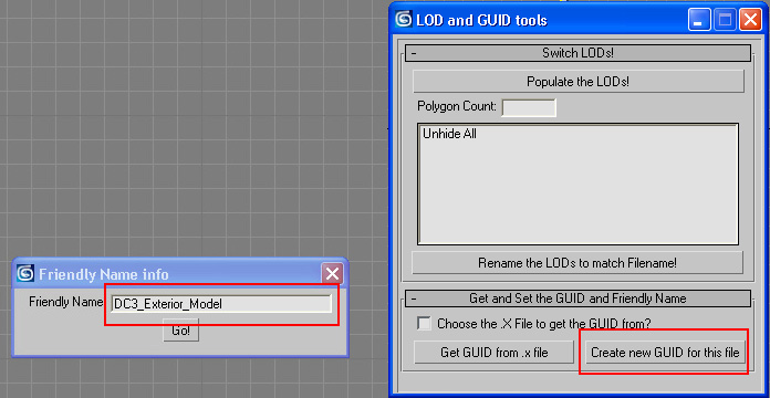
The model now has a friendly name and guid assigned to it which is kept in File >File Properties…>File Properties>Custom Tab>Properties.
.jpg)
The Exterior Model
Exterior Model Hierarchies
Triangle Counts
Specific Material Settings for Aircraft
- General Material
- Propeller
- Glass
- Chrome
- Skinned Meshes
- Tail Number
- LOD_5
Texture Naming
Animation System
Tagging
Untagging
Visibility Tags
Adding Lights
Adding Doors and Exits
Adding Pilots
Exterior Model Hierarchies
The top node is a dummy node placed at the origin. Directly beneath the top node are the LOD (level of detail) nodes which range from 400 (top LOD) to 5 (lowest LOD).
 |
All the geometry in LOD_150 and down have been removed for simplicity. Open the actual sample DC3 files to view the full hierarchy. |
Triangle Counts
LODs should be implemented in order to optimize performance. The following is the triangle count for the DC3. Obviously a 747 will need more triangles than a C-172 so use your best judgment. The more complex aircraft models provided with ESPhave approximately 25000 triangles for the LOD_400 model. Generally speaking LOD 35 and up will have animations while LOD 15 and below will not. Also LOD 5 is basically created using planar meshes.
| LOD_400 | 14000 |
| LOD_150 | 11000 |
| LOD_75 | 7000 |
| LOD_35 | 3000 |
| LOD_15 | 800 |
| LOD_5 | 50 |
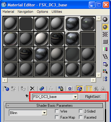
Specific Material Settings for Aircraft
Open the Material Editor; select an unused material slot; click on the material type button (Standard is default) which brings up the Material/Map Browser; select FlightSimX from the list and click OK, then rename the material to an appropriate name.
 |
General Material
General material is used for the main parts of an aircraft, where there is no alpha component.
- Assign the diffuse image by checking the Diffuse Color box and selecting an appropriate diffuse color map.
- Assign the specular image by checking the Specular Color box and selecting an appropriate specular map or assign the bump image by checking the Bump box and selecting an appropriate normal map.
- Under Fresnel Ramp assign Fresnel bitmap by clicking on map browser button and selecting an appropriate Fresnel map. Check the Reflection option box and check the Specular option box.
- Under Special Functionality, check the Blend environment by inverse of diffuse alpha box and the Use global environment map as reflection box, move the slider for Reflection Scale to 30, and move the slider for Specular Map Power Scale to 202.
- Under Bloom, check the Allow bloom box, move the slider for Specular Bloom Floor to 0.9, and move the slider for ambient light scale to 1.0.
.jpg) |
Propeller
This is used for propeller discs that have partial transparency.
- Assign the diffuse image by checking the Diffuse Color box and selecting an appropriate diffuse color map. In this case, the bitmap should have an alpha channel or transparency layer (32 bit).
- Under Bloom, check the Allow bloom box, move the slider for Specular Bloom Floor to 0.9, and move the slider for ambient light scale to 1.0.
- Under Framebuffer Blend, click on Set Default Transparent. Source Blend and Destination Blend are set to SrcAlph and InvSrcAlpha, respectively, and under Enhanced Parameters check No shadow, which should look better than a completely opaque shadow.
 |
Glass
Glass is used for windows and light lenses.
- Under Blinn Basic Parameters, set Opacity to a value less than 50%. For the DC3 sample a value of 46% is used. The lower the opacity, the more transparent the glass.
- Assign the diffuse image by checking the Diffuse Color box and selecting an appropriate diffuse color map.
- Assign the specular image by checking the Specular Color box and selecting an appropriate specular map or assign the bump image by checking the Bump box and selecting an appropriate normal map.
- Assign the reflection image by checking the Reflection box and selecting an appropriate normal map. Note that the sample DC3 uses the file GlobalEnv_AC_Chrome.dds file.
- Under Fresnel Ramp assign Fresnel bitmap by clicking on map browser button and selecting an appropriate Fresnel map. Check the Reflection option box and the Specular option box.
- Under Special Functionality, check the Blend environment by inverse of diffuse alpha box and the Use global environment map as reflection box, move the slider for Reflection Scale to 30, and move the slider for Specular Map Power Scale to 202.
- Under Bloom, check the Allow bloom box, move the slider for Specular Bloom Floor to 0.9, move the slider for ambient light scale to 1.0.
- Under Framebuffer Blend, click on Set Default Transparent. Source Blend and Destination Blend are set to SrcAlph and InvSrcAlpha, respectively.
 |
Chrome
Chrome is used for propeller spinners and landing gear sliders.
- Assign the diffuse image by checking the Diffuse Color box and selecting an appropriate diffuse color map.
- Assign the specular image by checking the Specular Color box and selecting an appropriate specular map or assign the bump image by checking the Bump box and selecting an appropriate normal map.
- Assign the reflection image by checking the Reflection box and selecting an appropriate normal map. Note that the sample DC3 uses the file GlobalEnv_AC_Chrome.dds file.
- Under Fresnel Ramp assign a bitmap by clicking on the map browser button and selecting an appropriate Fresnel map. Check the Reflection option box and the Specular option box.
- Under Special Functionality, check the Blend environment by inverse of diffuse alpha box and the Use global environment map as reflection box, move the slider for Reflection Scale to 30, move the slider for Specular Map Power Scale to 202.
- Under Bloom, check the Allow bloom box, move the slider for Specular Bloom Floor to 0.9, move the slider for ambient light scale to 1.0.
.jpg) |
Skinned meshes
Skinned meshes need a special material in order for the animation to work. This is essentially identical to the General Material with the addition of checking the Skinned mesh box under Enhanced Parameters:
 |
Tail number or N number
Tail numbers are used for ATC identification decals.
- Assign the diffuse image by checking the Diffuse Color box and selecting an appropriate diffuse color map. This map does not have to exist, but entering one is simply necessary for the tool to work.
- Under Fresnel Ramp it is not necessary to assign a bitmap but still check the Reflection option box and the Specular option box.
- Under Bloom: check the Allow bloom box, move the slider for Specular Bloom Floor to 0.9 and move the slider for ambient light scale to 1.0.
- Under Framebuffer Blend: click on Set Default Transparent. Source Blend and Destination Blend are set to SrcAlph and InvSrcAlpha, respectively.
- Under Aircraft Material Params: check the Is N-Number texture box near the bottom. This will assign the appropriate ATC identification or tail number.
.jpg) |
LOD_5
LOD 5 is the lowest level of detail and is created with flat polygons. There are no textures associated with it to minimize draw time. The only setting needed for this is under Enhanced Parameters – check the Double sided box:
 |
Texture Naming
Textures are organized using a simple naming convention, suffixes are used to delineate between the different kinds of texture maps:
- _T designates an exterior texture map and contains all the color information.
- _C designates a virtual cockpit texture map.
- _spec designates the specular texture map.
- _reflection designates the reflection map.
- _bump designates the bump map.
- _night designates the night map.
- _1, _2, _3 designates that there are a number of textures associated with that type of texture map.
- Decal_nnumber designates the tail number used for ATC identification. This file does not have to exist; but it is necessary to have some diffuse map reference in order for the FlightSimX material to work properly.
- fresnel_ramp designates the fresnel map.
Example 1: main texture maps for the DC3
- Douglas_DC3_1_T.psd
- Douglas_DC3_2_T.psd
Example 2: interior maps for night time for the DC3.
- Douglas_DC3_1_night_C.psd
- Douglas_DC3_2_night_C.psd
- Douglas_DC3_3_night_C.psd
- Douglas_DC3_4_night_C.psd
Note
Animated textures (or texture cycling) is not supported.
Animation System
All animations need to be key-framed because axis driven animations (such as rotations about an axis) are no longer supported. All rotational animations should be Linear, and not Euler or TCB. All objects with animations need to be associated to an animation tag (an animation variable), whether the object is a mesh, dummy node or bone. Also object names have no bearing on animations but are important for organization.
Refer to the file Animation Tags, for a full list of tags used by aircraft, and to the Creating a New Animation section of the Using Modeling Tools document.
Example: to animate and tag the rudder
Select the rudder; move the pivot to the axis of rotation; key the animation from 0-100…0 = full left, 50 = neutral, 100 = full right. The following sections on Tagging and Untagging use the rudder as an example.
Tagging
Open the Animation Tool: Aces Tools>AnimationManager.
Set the Start frame as 0 and the End frame as 100 (just below the Create and Delete buttons).
Under Animation List scroll down and find rudder_percent_key and select it.
Click on Create to associate the rudder_percent_key animation tag to the rudder mesh. Rudder_percent_key will show up in the Object Anims window and the Create button will get grayed out.
In the image below, the part name is listed in the top right corner and the animation tag rudder_percent_key has been associated to the part and the animation has a range of 0 – 100.
.jpg)
Look at the dope sheet to verify the animation tag has been associated to the rudder:

Untagging
To remove an association to an animation tag, and using the rudder example:
Select the rudder mesh.
Open the Animation Tool: Aces Tools>AnimationManager.
Click on Update Sel which will list rudder_percent_key in the Object Anims window.
Click on rudder_percent_key in the Object Anims window; this should highlight rudder_percent_key in the Animation List window.
Click on Delete. The rudder is now untagged and will not react to inputs when running the simulation.
Click on Update Sel to verify the animation tag has been disassociated. In the image below, notice that the Object Anims window is empty (which means there is no associated animation tag).
.jpg)
Visibility Tags
Object visibility can be controlled by associating a visibility tag to it. This is currently used on propellers, wheels, turbine fans, and similar machinery, to switch between different blur states to emulate motion blur.
Example: Setting propeller visibility on right slow propeller
There are three states for a propeller: still (still to slow), slow (slow to blurred) and blurred (very fast.).
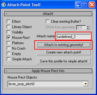
To set visibility tags:
- Select FS Tools>AttachPointTool.
- Check the Visibility box; which opens a drop-down menu of choices: select prop1_slow
- Under Attach!: click on Attach to existing geometry! The tool creates an attach name to the object according to the selection
- Verify by right clicking the object and selecting Properties>User Defined:
 |
.jpg) |
Adding Lights
Lights can be added using the AttachPoint Tool or by updating the aircraft configuration file. Most light effects can be added in two ways, depending on whether the light (or whatever the light is attached to) is static or dynamic. For most lights attached to a fixed part of a plane, simply add an entry in the aircraft configuration file, which contains all the necessary information to define the simulation model, including static lights. The following image shows the lights for the sample DC3, including a white navigation light, a beacon, and two interior lights.
.jpg) |
Note the use of "//" in the aircraft configuration file to add comments that help in understanding the file format. |
However if a light is attached to a moving part (including wings with flex) or if the light is a landing light, then we need to create an attach point for the light effect.
Example: Setting a green starboard light on a wing with flex
To add a light to a moving part:
Create a small one sided single poly mesh. This will be used to attach the light effect. In this case the light effect will be a blinking green running light.
Center the pivot point of the object. Wherever the center is placed is where the effect will show up.
Place the mesh at the right wingtip and link to the animated part (in this case a bone).


Open FS Tools>AttachPointTool and check the Effect box and the Visibility box. Under the Apply part visibility drop-down menu, the default is general light. Leave that as is. Under the Effect to Attach drop down menu, select fx_navgre (navigation green).
Click on Attach to existing geometry! Under Attach name the tool renames the actual object according to the selections.
.jpg)
Landing lights
Landing lights also need to be placed using the AttachPointTool.
Create a small one sided single poly mesh. This will be used to attach the light effect, in this case the light effect will be a landing light.
Center the pivot point of the object and rotate the pivot so Y is pointing in the direction of the light beam, X is toward the ground and Z is pointing starboard. This will ensure the cast light is shining forward. (see image below)
Place the mesh in front of the light source. In the sample DC3, the lights are located at the leading edges of the wings. Due to drawing issues, the attach point mesh should not be embedded within an opaque object since it will most likely get drawn behind that object. In the sample DC3, the attach point mesh is inside the translucent light housing but forward of the light mesh.

Open FS Tools>AttachPointTool and check the Effect box and Visibility box. Under the Apply part visibility drop-down menu, the default is general light. Leave that as is. Under the Attach Effect drop down menu, select fx_landing (landing light).
Under Attach! the tool renames the object according to the selections.
Click on Attach to existing geometry!
.jpg)
Adding Doors and Exits
Doors, exits, cargo doors need to be included in the aircraft configuration file after they have been animated and tagged in 3ds max. In the sample DC3, the door linkages and handle have all been animated with keyframes from 0 – 100 and tagged to door_0.
 |
.jpg) |
In earlier versions of ESP f_canopy (forward canopy) and r_canopy (rear canopy) were used to designate doors and exits, later models use door_0 to door_3 for simplicity. By using discrete door animation tags, doors can be opened and closed by type. Use the following animation tags to delineate between different kinds of doors and exits:
- door_0: main doors or exits
- door_1: cargo doors
- door_2: emergency doors
- door_3: miscellaneous
When the door is animated and tagged, add an entry to the corresponding aircraft configuration file:
.jpg) |
Shadow mapping
Shadow maps or cast shadows are automatically generated for aircraft exteriors by default. In order to turn off shadows (which is recommended on parts with partial transparency, such as propeller discs) simply check the No shadow box under Enhanced Parameters. The image below shows a proplellor disc material with shadows turned off.
 |
Adding Pilots
Pilots are part of the aircraft hierarchy just like any other part. Most pilots will have several common animations such as turning the yoke left or right, pulling the yoke fore and aft, throttling up or down, pushing the rudder pedals, turning their heads in the direction of a turn, and so on. They can be animated in one of two ways: rigid meshes or skinning. Rigid mesh and skinned/bone meshes are supported, with the following characteristics:
Rigid meshes
Translation in x, y, and z.
Rotation in x, y, z; linear rotation is recommended.
Scaling is currently not supported.
Dummy nodes are supported, and are useful for separating animations from meshes and for preserving animations throughout LODs.
Skinned/boned meshes
Skin animation is used for some pilots and wing flex on aircraft, although the DC3 sample has rigid mesh pilots. Skin animation pilots should only be used on aircraft where the pilots are more visible.
Animating a skinned pilot is essentially the same as animating rigid meshes except that bones are tagged, rather than meshes.
There is a limit of 128 bones per model, and a limit of 22 connected bones. Any one vertex of a model can be influenced by a maximum of four bones. Models will fail if they exceed these limits.
To animate the forearm of a rigid mesh pilot
Since the arm needs to be part of the elevator up/down animation as well as aileron left/right animation, it needs to incorporate a dummy node for each section of the arm. The dummy will have the elevator up/down animation and the actual arm parts will have the aileron left/right animation.
Animate the parts from keyframe 0 - 100.
When the animations are done, associate animation tags. First select the elbow dummy.
Open the Animation Tool: FS Tools>AnimationManager.
In the Start box enter 0 and in the End box enter 100.
In the Animation List, select lever_stick_fore_aft.
Click on Create. You will notice the Create button is now grayed out to show that that animation variable is already assigned to that part.
.jpg)
Next select the forearm mesh.
Click on the Update Sel button. Note that 0 and 100 should still be the start and end keyframes.
In the Animation List, select lever_stick_l_r.
Click on Create. Both parts should be tagged appropriately and should animate in the product.
The Animation Tool will not automatically update when selecting different objects while the tool is open. You will need to click on the Update Sel button each and every time you select a new object in order for the tool to update.

The Interior Model
Interior Model Hierarchies
Virtual Cockpit Specific Materials
- Windshield
- Gauges
Interior Animation Tagging
Mouse Rectangle Tags
Updating the Panel Configuration File
Interior Model Hierarchies
The hierarchy for the virtual cockpit is not very different from the exterior model. The top object, in this case the dummy object, is placed at the same center point as the exterior model. Scaling of the top object should be set to 100% and translations should be set to 0,0,0. The real difference is that there are no LOD hierarchies in the virtual cockpit model.
.jpg) |
Note
The sample Douglas DC3 virtual cockpit has a triangle count of around 10,000 including exterior parts. The texture counts are two 1024 maps, four 512 maps and two 256 maps including gauges and self illumination maps. Most of the geometry outside the view angles of the initial eye-point range have been deleted to improve performance. Some of the more complex aircraft interiors have a triangle count of around 24,000 and have perhaps ten 1024 maps including gauges and self illumination maps. We would recommend that content creators use these estimates as upper limits and to understand that greater increases in triangle and texture counts will result in performance loss.
Virtual Cockpit Specific Materials
Due to the increase in base textures and self illumination maps, specular and bump maps have not been implemented in the DC3. The base materials for the DC3 virtual cockpit only have a few specific settings.
- Choose the base texture in the Diffuse color map section.
- Choose the night version of the base texture (not name specific) in the Self- Illumination map section.
- Choose BlendUserControlled in the Emissive Mode section.
- Check the No Base Material Specular box if there is no specular map.
 |
Windshield
The windshield material for the DC3 virtual cockpit has alpha settings but no self illumination map.
- Choose the base texture in the Diffuse color map section.
- Select the Select Default Transparent button in the Framebuffer Blend dialog.
- Check the Set final alpha value at render time box and set the Final Alpha Multiply slider to the level desired. In this case the windshield is set to 15% opaque.
- Check the No Base Material Specular box if there is no specular map.
.jpg) |
Gauges
The gauge materials for the DC3 virtual cockpit have an additional setting in the Aircraft Materials Params section.
- Choose the gauge texture in the Diffuse color map section.
- Choose the same gauge texture in the Self-Illumination map section.
- Select the Select Default Transparent button in the Framebuffer Blend dialog.
- Choose BlendUserControlled in the Emissive Mode section.
- Check the No Base Material Specular box.
- Check the Is virtual cockpit panel texture box in the Aircraft Material Params section.
|
Note: Z-Fighting in Gauge Textures
It is possible that some of the gauge texture sheets will encounter Z-buffer fighting issues. This issue can be addressed with additional settings. If you are experiencing Z fighting issues with gauge texture sheets, try applying the following change in the material and re-export.
- Select the Set Default Opaque button in the Framebuffer Blend dialog.
- Check the Z-Test Alpha box in the Material Alpha Test dialog.
- Set the Alpha Test Level slider greater than 128.
- Select Greater in the Alpha Test Mode drop-down dialog.
.jpg) |
Assigning Gauges in the Virtual Cockpit
If a texture name starts with “$” then the texture is assumed to be a virtual cockpit (VC) gauge texture. This texture serves as a specific coordinate reference on a virtual texture sheet which maps the 2D bitmap panel gauges on the sheet in real time. The reference to the 2D panel bitmaps is done through the panel configuration file of the aircraft. A texture sheet with “$” or is not needed once the model is exported out of 3ds max.
To assign gauges in the Virtual Cockpit:
- Create the geometry for the gauges.
- Create a texture sheet that shows the edges of the gauges for precise mapping. Be sure that it has a $ prefix. When laying out this texture, write down the size of the each gauge along with the coordinates of the top left pixel of the image. This information will be used in panel.cfg file.
- Map the texture onto the geometry as you normally would using UVW Map and the UVW Unwrap in the UV Coordinate Modifier stack.
 |
Interior Animation Tagging
For information on the aircraft specific animations, refer to the Animation Tags document, and to the Creating a New Animation section of the Using Modeling Tools document.
Here are the steps that you will need to follow to add animation tags to animated objects.
Select the object that has been properly keyframed (linear animations).
Open the animation tagging tool via FSTools >AnimationManager.
Click the Update Sel button, select the proper animation tag name from the Animation List and enter the keyframe length in the Start and End boxes. It is important to note that starting and ending times references which keyframes have the specific animation information. For example, if the length of animation is 75 keyframes, the animation could run from keyframes 25-100. You do not have to start keyframe animation at keyframe 0.
.jpg)
Click the Create button and the animation tag name should appear in the Object Anims list. It is important to note that when tagging multiple items, be sure and press the Update Sel button to refresh the tool.
.jpg)
The animation information from the AnimationManager tool is stored in the notetrack information for the part in the dope sheet. To access the dope sheet, select the object and select the tool: Graph Editors >Track View – Dope Sheet. You should see the animation tag name under the Transform section in the Notes category.

Mouse Rectangle Tags
Mouse rectangle tagging information links an animated tagged object with the mouse pointer. For greater control, this feature is separated from the animation tagging process.
To implement mouse rectangles, select the object and select the tool via Aces Tools >AttachPointTool.
Check the Mouse Rect box and select the mouse rectangle name from the Mouse Rect Objects: dropdown menu. The naming convention is the same as in the animation tagging tool.

Select the Attach to existing geometry! button and a name should appear in the Attach name box. This name has no affect on the mouse rectangle information and therefore does not need to be changed from the default naming.
The mouse rect information is stored in the Object Properties dialog box. To access this information select Edit>Object Properties…>Object Properties dialog box>User Definedtab>User Defined Properties.
.jpg)
Updating the Panel Configuration File
This section shows how to assign panel textures in a panel configuration file.
Open the panel configuration fileof the aircraft which you are modeling. In this case, we will work with the DC3.
Create a section for the virtual cockpit under the last window reference section.
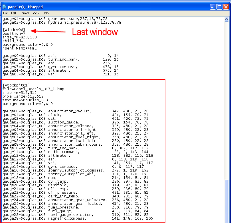
It is very important to follow the exact naming structure:
[VCockpit01]= first texture sheet for virtual cockpit.
File= A texture can be placed as the base of the texture sheet replacing the transparent color. Note, currently there is no functionality to switch this background texture while the simualtion is running, for purposes such as night lighting.
Size_mm= size of texture sheet.
Pixel_size= size of texture sheet.
Texture= name of texture sheet ($ is the equivalent to _panel_).
Background_color= should be 0,0,0 which is transparent.For the list of gauges, each gauge number needs to be unique per texture section in the config file. If the numbers repeat, they will not draw in the simulation.
Gauge#= enter the exact name of the gauge from the panel section.
The numbers that follow the gauge name are listed in specific order. To get this information, you will need to open the texture in a program such as Paint.
1st Number = X coordinate of top left pixel in gauge bitmap.
2nd Number = Y coordinate of top left pixel in gauge bitmap.
3rd Number = width of gauge on texture sheet.
4th Number = height of gauge on texture sheet..
When the model is exported, it will have all of the information for the texture sheets. No “$” sheets are needed in the texture folder once the aircraft is complete. The physical texture sheets are only for laying out the gauges.
Notes
- To assign virtual cockpit eye-points in aircraft config, set the eye-point for the virtual cockpit through the aircraft configuration file under the view section:
 |
- The model config in the model folder now supports two .mdl files: Normal= exterior model, Interior= interior model.
 |
.jpg) |
- The texture config in a texture folder allows the content creator to have fallback directories that may contain duplicated textures. This process decreases the amount of space needed to create aircraft containers. Fallback texture files do not override textures found in the texture folder originally being called.
Fallback.#= supplemental texture directories outside of root texture folder
.jpg)