Connect your sensor to the Sharks Cove board
This topic provides guidance on how to connect your sensor test board to the Sharks Cove board.
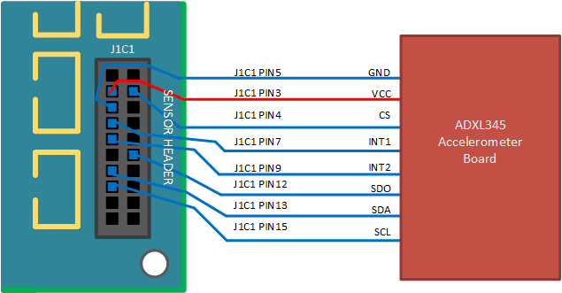
In the ADXL345 accelerometer scenario, and after making any necessary modifications, you would end up with the accelerometer test board connected to Sharks Cove as shown in the following diagram.
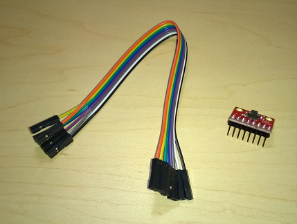
To achieve a stable and reliable connection between the sensor breakout board and the Sharks Cove, you could start by soldering an 8-pin single-row male header to the breakout board, as shown in the following image.

Then use a ribbon of eight female-to-female jumper wires (shown below), to connect the sensor breakout board to the Sharks Cove, based on the preceding connection diagram.
Here are some examples of how information from the ADXL345 data sheet, and the Sharks Cove Technical Specifications Rev. 1.0, helped us to arrive at the connection strategy shown in the preceding diagram:
J1C1 PIN4 connected to VDD and CS on the accelerometer board.
- VDD is the supply voltage line for the Digital Interface. We decided to use the accelerometer in dual-voltage configuration, and also keep the power consumption low. So out of the four available voltages (J1C1 PIN1 - PIN4) we targeted the two lowest ones. These are 2.8V on J1C1 PIN3 and 1.8V on J1C1 PIN4. In dual-voltage configuration, VDD must be connected to a lower voltage than VS. So we've connected VDD to J1C1 PIN4, the 1.8V line on Sharks Cove.
- CS is the communication mode selection pin for the accelerometer. To enable the I2C communication mode, you must tie CS high, in this case to VDD, which is taken care of by the modification with the blue wire in Prepare your sensor test board. The modification ties both VDD and CS from the accelerometer board to J1C1 PIN4, the 1.8V line.
J1C1 PIN12 connected to SDO on the accelerometer board.
- When the SDO line is high, the 7-bit I2C address for the accelerometer board is 0x1D, followed by the R/W bit. When the SDO line is low (i.e. connected to Ground), the I2C address for the accelerometer board is 0x53, followed by the R/W bit. In the Microsoft SPBAccelerometer sample, it was decided that the address of 0x53 would be used. And that's why the SDO line is connected to a Ground pin (J1C1 PIN12) on Sharks Cove.
The connection decisions outlined in the preceding bullets were based on information from the Theory of Operation section (page 6) and the Serial Communications section (page 8) of the ADXL345 data sheet.
After successfully connecting your sensor test board to Sharks Cove, read the next topic for guidance on how to write and deploy your universal sensor driver.
Feedback
Coming soon: Throughout 2024 we will be phasing out GitHub Issues as the feedback mechanism for content and replacing it with a new feedback system. For more information see: https://aka.ms/ContentUserFeedback.
Submit and view feedback for