Filtering data (previous version)
In order to optimize data throughput, your sensor device must apply filter criteria to the data-update events so that they're only raised when needed. This filtering results in lower CPU utilization (due to reduced sensor throughput) and less power consumption (both for the sensor and the CPU).
There are two values (or properties) that support a sensor device's filter criteria. The first is the current report interval (CRI) and the second is the change sensitivity (CS). Both of these properties can be set by a sensor application.
The current report interval is the minimum period, in milliseconds, between data updates that a client wishes to receive when meaningful change has occurred. The change sensitivity is the value (or percentage) used to specify meaningful change.
A weather-station application may specify a current report interval (CRI) for a temperature sensor of 60,000 (one minute). The temperature sensor would require a change-sensitivity value (as opposed to a percentage). If this temperature sensor returns degrees Celsius and the change sensitivity value temperature was 2.0, this particular sensor would only raise the data-updated event when the temperature increased, or decreased, by 2.0 degrees Celsius over the requested report interval.
An ambient light sensor (ALS) is an example of a sensor that would require change-sensitivity to be specified as a percentage. For example, if the change sensitivity value for Illuminance was 2.0, this sensor would interpret the value as a percentage and only raise the data-updated event when the LUX value had either dropped or increased by 2%.
The following table lists six common sensors, the data associated with each, and the corresponding change sensitivity.
| Sensor | Data field | Change sensitivity value |
|---|---|---|
| Light Sensor | LUX | % change in lux |
| Accelerometer | Acceleration X | Acceleration G-force |
| Acceleration Y | Acceleration G-force | |
| Acceleration Z | Acceleration G-force | |
| 3D Gyrometer | Angular Speed X | Angular Speed (degrees per second) |
| Angular Speed Y | Angular Speed (degrees per second) | |
| Angular Speed Z | Angular Speed (degrees per second) | |
| Compass | Magnetic North Heading | Degrees |
| True North Heading | Degrees | |
| Inclinometer | Yaw | Degrees |
| Pitch | Degrees | |
| Roll | Degrees | |
| Device Orientation | Quaternion | Degrees Movement |
| Rotation Matrix | Degrees Movement |
The following table lists the recommended current report interval (CRI) defaults.
| Sensor type | Recommended default report interval |
|---|---|
| Ambient Light | 5000 |
| Accelerometer | 100 |
| Gyrometer | 100 |
| Compass | 100 |
| Inclinometer | 50 |
| Orientation | 50 |
The following table lists the recommended change sensitivity (CS) defaults.
| Sensor type | Recommended default change sensitivity |
|---|---|
| Ambient Light | 50 |
| Accelerometer | 0.02 |
| Gyrometer | 0.50 |
| Compass | 0.20 |
| Inclinometer | 0.50 |
| Orientation | 0.50 |
Change sensitivity (CS) for the inclinometer and orientation sensors
Change sensitivity for the inclinometer and orientation sensor should be calculated as the angle between two quaternions. Mathematically expressed as:
2*cos⁻1(dot product(q1, q2))
This calculation ensures consistency across device orientations.
Effective current report interval (CRI) and change sensitivity (CS)
Multiple applications can set both the Current Report Interval (CRI) and the Change Sensitivity (CS) properties for a given sensor. It's the responsibility of your driver to determine which requested property applies. The properties set by the driver are referred to as the Effective Current Report-Interval (E-CRI) and the Effective Change-Sensitivity (E-CS).
Setting the E-CRI and E-CS for client applications
Whenever a client application establishes a connection to a sensor, your driver needs to set the E-CRI and E-CS values. These values are stored in what's referred to as a client container. The following table lists six methods supported by a sensor driver and specifies what your driver should do with its client container and the E-CRI and E-CS properties.
| Event of interest | Event handler activities |
|---|---|
| ISensorDriver::OnClientConnect | Add client item to client containerRead default CRI and CS values as appropriate, store in client container |
| ISensorDriver::OnClientDisconnect | Remove client from client container and set the E-CRI and E-CS as appropriate based on the remaining clients |
| ISensorDriver::OnClientSubscribeToEvents | Update "subscribed to events" field – (set to true) for the sensor in question. Turn on event reporting from the sensor. |
| ISensorDriver::OnClientUnSubscribeToEvents | Update "subscribed to events" field – (set to false) for the sensor in question. If no subscribers remain, turn off event reporting from the device. |
| ISensorDriver::OnSetProperties | If CS or CRI properties are set, update appropriate client container fields. |
| IFileCallbackCleanup::OnCleanupFile | The client has crashed or stopped responding. The client should be removed from the client container. |
The following table represents the client container for a 3D accelerometer with four connected client applications. Two of these client apps (corresponding to the 2nd and 4th row) have subscribed to events.
| Client file handle | Subscribed to events | CRI | CS (X) | CX (Y) | CS (Z) |
|---|---|---|---|---|---|
| FF80A267 | FALSE | 50 | 0.001 | 0.001 | 0.001 |
| FF802489 | TRUE | 70 | 0.02 | 0.02 | 0.02 |
| FF80D345 | FALSE | 15 | NULL | NULL | NULL |
| FF803287 | TRUE | 100 | 0.005 | 0.005 | 0.005 |
After the driver evaluated this set of connected clients, it chose the following values for E-CRI and E-CS:
- E-CRI: 70 ms
- E-CS values: (could collapse to single value using smallest threshold)
- X:0.005
- Y:0.005
- Z: 0.005
Notice in this example that clients that don't have an event sink set (first and third rows) are disregarded since event filtering doesn't apply to those clients.
Filtering data update events by evaluating the effective CRI and CS values (E-CRI, E-CS)
Once the current E-CRI and E-CS values have been determined and are updated as sensor connection states change, your sensor device will use these values to filter events that are raised to connected client applications. These values are compared against the difference between the "current" data value(s) and the previous data value(s). If the E-CS values have been exceeded for a time period equal to or greater than the E-CRI, only then should a data event be raised. The only exception is sensor device startup, when the default value(s) are applied so that clients can receive the proper notification.
The following illustration demonstrates how time filtering of raw sensor data is evaluated in order to determine when data events should be raised.
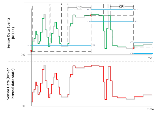
In the previous illustration, the red data in the lower portion of the diagram represents the raw sensor data. The green line represents data that would be returned to clients that poll for data (one of many ways to implement this behavior) and the red X values represent when data events are fired. Blue lines are the thresholds for the E-CS boundaries (+/- E-CS relative to last data event value).
By implementing this event filtering logic, the number of data updated events can be greatly reduced, and applications can still get notified when meaningful changes in sensor data occur.
Device runtime optimizations for data filtering
This section describes several runtime optimizations you should consider as you develop a sensor driver.
Support interrupts
Your driver should rely on interrupts instead of polling the device. This will result in performance and power-management improvements. These improvements include the following.
- Your device can enter a lower power state based on the current change sensitivity and report interval.
- Using interrupts will reduce unnecessary code execution in both the driver and the sensor firmware.
- Using interrupts will reduce bus activity.
Note
If a driver relies on interrupts but the current report interval and change-sensitivity logic exists in the driver, the driver will potentially receive a significant number of interrupts between data updates. As a result, the driver may need to disable (or mask) interrupts until the current-report interval expires.
Move change-sensitivity support to the device
If your sensor hardware, or firmware, supports threshold detection you should use this feature to support change sensitivity. By moving the support to the device, and then responding to the corresponding interrupt, you reduce processing overhead in your driver.
Move report-interval support to the devices
If your sensor hardware, or firmware, supports the notion of a report interval you should use this feature.
If your sensor doesn't provide native report-interval support, consider disabling interrupts for a subset of the current report interval. Then, once this time elapses, retrieve the current device data.
Related topics
Feedback
Coming soon: Throughout 2024 we will be phasing out GitHub Issues as the feedback mechanism for content and replacing it with a new feedback system. For more information see: https://aka.ms/ContentUserFeedback.
Submit and view feedback for