Create a geo-redundant, multi-data center RDS deployment for disaster recovery
Applies to: Windows Server 2022, Windows Server 2019, Windows Server 2016
You can enable disaster recovery for your Remote Desktop Services deployment by leveraging multiple data centers in Azure. Unlike a standard highly available RDS deployment (as outlined in the Remote Desktop Services architecture), which uses data centers in a single Azure region (for example, Western Europe), a multi-data center deployment uses data centers in multiple geographic locations, increasing the availability of your deployment - one Azure data center might be unavailable, but it is unlikely that multiple regions would go down at the same time. By deploying a geo-redundant RDS architecture, you can enable failover in the case of catastrophic failure of an entire region.
You can use the instructions below to leverage Microsoft Azure infrastructure services and RDS to deliver geo-redundant desktop hosting services and Subscriber Access Licenses (SALs) to multiple tenants through the Microsoft Service Provider License Agreement (SPLA) program. You can also use the steps below to create a geo-redundant hosting service for your own employees using RDS User CALs extended rights through Software Assurance.
Logical architecture for high availability - single and multiple regions
The following image shows the architecture for a highly available deployment in a single Azure region:
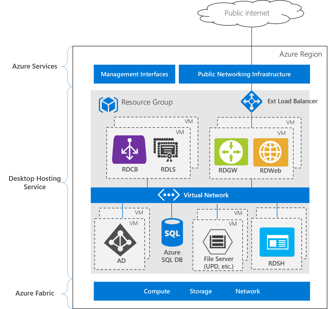
The deployment consists of three layers:
- Azure services - the Azure Management interfaces, including the Azure portal and APIs, and public networking services, such as DNS and public IP addressing.
- Desktop hosting service - Virtual machines, networks, storage, Azure services, and Windows Server role services
- Azure Fabric - Windows Server operating systems running the Hyper-V role, used to virtualize physical servers, storage units, network switches, and routers. Using Azure Fabric lets you create VMs, networks, storage, and applications independent from underlying hardware.
In comparison, here is the architecture for a deployment that uses multiple Azure data centers:
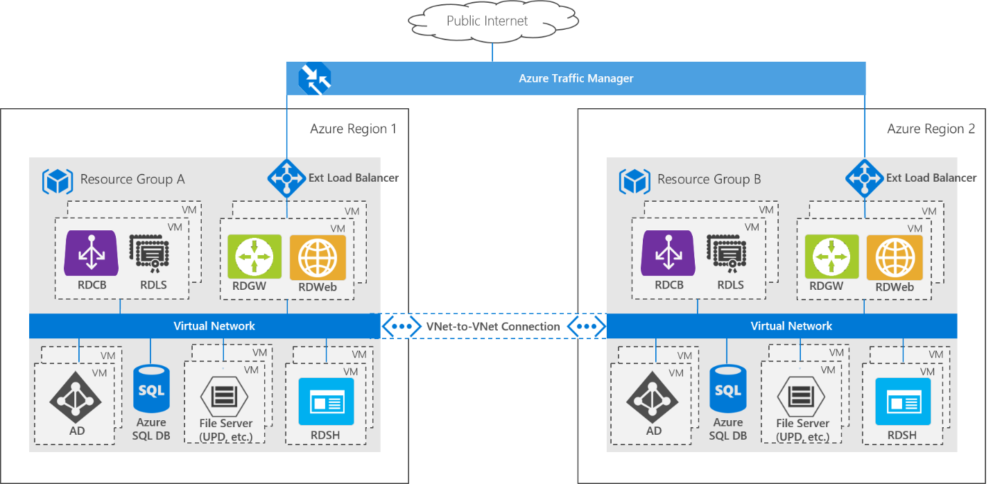
The entire RDS deployment is replicated in a second Azure region to create a geo-redundant deployment. This architecture uses an active-passive model, where only one RDS deployment is running at a time. A VNet-to-VNet connection lets the two environments communicate with each other. The RDS deployments are based on a single Active Directory forest/domain, and the AD servers replicate across the two deployments, meaning users can sign into either deployment using the same credentials. User settings and data stored in User Profile Disks (UPD) are stored on a two-node cluster Storage Spaces Direct scale-out file server (SOFS). A second identical Storage Spaces Direct cluster is deployed in the second (passive) region, and Storage Replica is used to replicate the user profiles from the active to passive deployment. Azure Traffic Manager is used to automatically direct end users to whichever deployment is currently active - from the end user perspective, they access the deployment using a single URL and are not aware of which region they end up using.
You could create a non-highly available RDS deployment in each region, but if even a single VM is restarted in one region, a failover would occur, increasing the likelihood of failovers occurring with associated performance impacts.
Deployment steps
Create the following resources in Azure to create a geo-redundant multi-data center RDS deployment:
Two resource groups in two separate Azure regions. For example RG A (the active deployment, RG stands for "resource group") and RG B (the passive deployment).
A highly-available Active Directory deployment in RG A. You can use the New AD Domain with 2 Domain Controllers template to create the deployment.
A highly-available RDS deployment in RG A. Use the RDS farm deployment using existing active directory template to create the basic RDS deployment, and then follow the information in Remote Desktop Services - High availability to configure the other RDS components for high availability.
A VNet in RG B - make sure to use an address space that does not overlap the deployment in RG A.
A VNet-to-VNet connection between the two resource groups.
Two AD virtual machines in an availability set in RG B - make sure the VM names are different from the AD VMs in RG A. Deploy two Windows Server 2016 VMs in a single availability set, install the Active Directory Domain Services role, and then promote them to the domain controller in the domain you created in step 1.
A second highly-available RDS deployment in RG B.
- Use the RDS farm deployment using existing active directory template again, but this time make the following changes. (To customize the template, select it in the gallery, click Deploy to Azure and then Edit template.)
Adjust the address space of the DNS server private IP to correspond to the VNet in RG B.
Search for "dnsServerPrivateIp" in variables. Edit the default IP (10.0.0.4) to correspond to the address space you defined in the VNet in RG B.
Edit the computer names so that they don't collide with those in the deployment in RG A.
Locate the VMs in the Resources section of the template. Change the computerName field under osProfile. For example, "gateway" can become"gateway-b"; "[concat('rdsh-', copyIndex())]" can become "[concat('rdsh-b-', copyIndex())]", and "broker" can become "broker-b".
(You can also change the names of the VMs manually after you run the template.)
- As in step 3 above, use the information in Remote Desktop Services - High availability to configure the other RDS components for high availability.
- Use the RDS farm deployment using existing active directory template again, but this time make the following changes. (To customize the template, select it in the gallery, click Deploy to Azure and then Edit template.)
A Storage Spaces Direct scale-out file server with Storage Replica across the two deployments. Use the PowerShell script to deploy the template across the resource groups.
Note
You can provision storage manually (instead of using the PowerShell script and template):
- Deploy a two-node Storage Spaces Direct SOFS in RG A to store your user profile disks (UPDs).
- Deploy a second, identical Storage Spaces Direct SOFS in RG B - make sure to use the same amount of storage in each cluster.
- Set up Storage Replica with asynchronous replication between the two.
Enable UPDs
Storage Replica replicates data from a source volume (associated with the primary/active deployment) to a destination volume (associated with the secondary/passive deployment). By design, the destination cluster appears as Online (No Access) - Storage Replica dismounts the destination volumes and their drive letters or mount points. This means that enabling UPDs for the secondary deployment by providing the file share path will fail, because the volume is not mounted.
Want to learn more about managing replication? Check out Cluster to cluster Storage Replication.
To enable UPDs on both deployments, do the following:
Run the Set-RDSessionCollectionConfiguration cmdlet to enable the user profile disks for the primary (active) deployment - provide a path to the file share on the source volume (which you created in Step 7 in the deployment steps).
Reverse the Storage Replica direction so that the destination volume becomes the source volume (this mounts the volume and makes it accessible by the secondary deployment). You can run Set-SRPartnership cmdlet to do this. For example:
Set-SRPartnership -NewSourceComputerName "cluster-b-s2d-c" -SourceRGName "cluster-b-s2d-c" -DestinationComputerName "cluster-a-s2d-c" -DestinationRGName "cluster-a-s2d-c"Enable the user profile disks in the secondary (passive) deployment. Use the same steps as you did for the primary deployment, in step 1.
Reverse the Storage Replica direction again, so the original source volume is again the source volume in the SR Partnership, and the primary deployment can access the file share. For example:
Set-SRPartnership -NewSourceComputerName "cluster-a-s2d-c" -SourceRGName "cluster-a-s2d-c" -DestinationComputerName "cluster-b-s2d-c" -DestinationRGName "cluster-b-s2d-c"
Azure Traffic Manager
Create an Azure Traffic Manager profile, and make sure to select the Priority routing method. Set the two endpoints to the public IP addresses of each deployment. Under Configuration, change the protocol to HTTPS (instead of HTTP) and the port to 443 (instead of 80). Take note of the DNS time to live, and set it appropriately for your failover needs.
Note that Traffic Manager requires endpoints to return 200 OK in response to a GET request in order to be marked as "healthy." The publicIP object created from the RDS templates will function, but do not add a path addendum. Instead, you can give end users the Traffic Manager URL with "/RDWeb" appended, for example: http://deployment.trafficmanager.net/RDWeb
By deploying Azure Traffic Manager with the Priority routing method, you prevent end users from accessing the passive deployment while the active deployment is functional. If end users access the passive deployment and the Storage Replica direction hasn't been switched for failover, the user sign-in hangs as the deployment tries and fails to access the file share on the passive Storage Spaces Direct cluster - eventually the deployment will give up and give the user a temporary profile.
Deallocate VMs to save resources
After you configure both deployments, you can optionally shut down and deallocate the secondary RDS infrastructure and RDSH VMs to save cost on these VMs. The Storage Spaces Direct SOFS and AD server VMs must always stay running in the secondary/passive deployment to enable user account and profile synchronization.
When a failover occurs, you'll need to start the deallocated VMs. This deployment configuration has the advantage of being lower cost, but at the expense of fail-over time. If a catastrophic failure occurs in the active deployment, you'll have to manually start the passive deployment, or you'll need an automation script to detect the failure and start the passive deployment automatically. In either case, it may take several minutes to get the passive deployment running and available for users to sign in, resulting in some downtime for the service. This downtime depends on the amount of time it takes to start the RDS infrastructure and RDSH VMs (typically 2-4 minutes, if the VMs are started in parallel rather than serially), and the time to bring the passive cluster online (which depends on the size of the cluster, typically 2-4 minutes for a 2-node cluster with 2 disks per node).
Active Directory
The Active Directory servers in each deployment are replicas within the same Forest/Domain. Active Directory has a built-in synchronization protocol to keep the four domain controllers in sync. However, there may be some lag so that if a new user is added to one AD server, it may take some time to replicate across all the AD servers in the two deployments. Consequently, be sure to warn users to not try to sign in immediately after being added to the domain.
RD License Server
Provide a per-user RD CAL for each named user that is authorized to access the geo-redundant deployment. Distribute the per user CALs evenly across the two RD License Servers in the active deployment. Then, duplicate these CALs to the two RD License Servers in the passive deployment. Because the CALs are duplicated between the active and passive deployment, at any given time only one deployment can be active with users connecting; otherwise, you violate the license agreement.
Image Management
As you update your RDSH images to provide software updates or new applications, you'll need to separately update the RDSH collections in each deployment to maintain a common user experience across both deployments. You can use the Update RDSH collection template, but note that the passive deployment's RDS infrastructure and RDSH VMs must be running to run the template.
Failover
In the case of the Active-Passive deployment, failover requires you to start the VMs of the secondary deployment. You can do this manually or with an automation script. In the case of a catastrophic failover of the Storage Spaces Direct SOFS, change the Storage Replica partnership direction, so that the destination volume becomes the source volume. For example:
Set-SRPartnership -NewSourceComputerName "cluster-b-s2d-c" -SourceRGName "cluster-b-s2d-c" -DestinationComputerName "cluster-a-s2d-c" -DestinationRGName "cluster-a-s2d-c"
You can learn more in Cluster to cluster Storage Replication.
Azure Traffic Manager automatically recognizes that the primary deployment failed and that the secondary deployment is healthy (in the RD Gateway VMs have been started in RG B) and directs user traffic to the secondary deployment. Users can use the same Traffic Manager URL to continue working on their remote resources, enjoying a consistent experience. Note that the client DNS cache will not update the record for the duration of the TTL set in Azure Traffic Manager configuration.
Test failover
In a Storage Replica partnership, only one volume (the source) can be active at a time. This means when you switch the SR Partnership direction, the volume in the primary deployment (RG A) becomes the destination of replication and is therefore hidden. Thus, any users connecting to RG A will no longer have access to their UPDs stored on the SOFS in RG A.
To test the failover while allowing users to continue logging in:
Start the infrastructure VMs and RDSH VMs in RG B.
Switch the SR Partnership direction (cluster-b-s2d-c becomes the source volume).
Disable the endpoint of RG A in the Azure Traffic Manager profile to force the ATM to direct traffic to RG B. Alternatively, use a PowerShell script:
Disable-AzureRmTrafficManagerEndpoint -Name publicIpA -Type AzureEndpoints -ProfileName MyTrafficManagerProfile -ResourceGroupName RGA -Force
RG B is now the active primary deployment. To switch back to RG A as the primary deployment:
Switch the SR Partnership direction (cluster-a-s2d-c becomes the source volume):
Set-SRPartnership -NewSourceComputerName "cluster-a-s2d-c" -SourceRGName "cluster-a-s2d-c" -DestinationComputerName "cluster-b-s2d-c" -DestinationRGName "cluster-b-s2d-c"Re-enable the endpoint of RG A in the Azure Traffic Manager profile:
Enable-AzureRmTrafficManagerEndpoint -Name publicIpA -Type AzureEndpoints -ProfileName MyTrafficManagerProfile -ResourceGroupName RGA
Considerations for on-premises deployments
While an on-premises deployment couldn't use the Azure Quickstart Templates referenced in this article, you can implement all the infrastructure roles manually. In an on-premises deployment where cost is not driven by Azure consumption, consider using an active-active model for quicker failover.
You can use Azure Traffic Manager with on-premises endpoints, but it requires an Azure subscription. Alternatively, for the DNS provided to end users, give them a CNAME record that simply directs users to the primary deployment. In the case of failover, modify the DNS CNAME record to redirect to the secondary deployment. In this way, the end user uses a single URL, just like with Azure Traffic Manager, that directs the user to the appropriate deployment.
If you are interested in creating an on-premises-to-Azure-site model, consider using Azure Site Recovery.
Feedback
Coming soon: Throughout 2024 we will be phasing out GitHub Issues as the feedback mechanism for content and replacing it with a new feedback system. For more information see: https://aka.ms/ContentUserFeedback.
Submit and view feedback for