MT3620 Support Status
This document describes the current status of Azure Sphere support for the MediaTek MT3620. You may also want to refer to the MT3620 Product Brief, which is available for download on the MediaTek MT3620 web page. In addition, MediaTek produces the MT3620 Hardware User Guide, which is a detailed guide to integrating the MT3620 MCU into your own hardware.
Important
In the context of this document, not currently supported means that customer use of the feature is restricted at the current time, and this restriction is likely to be removed in the future. Conversely, not accessible means that the feature cannot be used by customers, and this restriction is unlikely to change.
If you have feature requests or feedback, we welcome your comments on the Azure Sphere community forum.
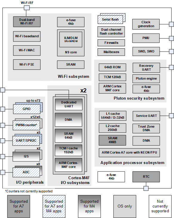
MT3620 block diagram
The block diagram shows the support provided for each MT3620 component. The sections that follow the diagram provide additional details about these components.
I/O peripherals
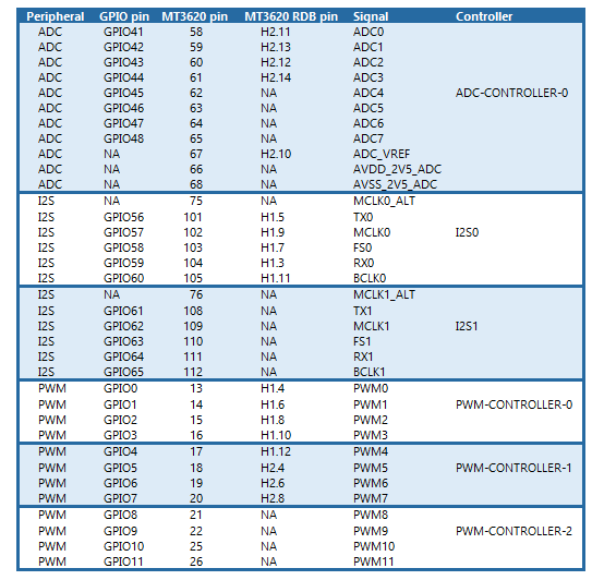
The MT3620 design includes a total of 76 programmable I/O pins. As shown in the following two tables, most of the pins are multiplexed between general-purpose I/O (GPIO) and other functions. In addition to the GPIO pins listed, GPIO12-23 are available on MT3620 pins 27-38 respectively.
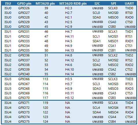
Referring to the following table, pins marked "UNUSED" are not used by the associated ISU peripheral and can be configured for use as GPIO pins.
Note
Once an ISU peripheral has been allocated to a core, all 5 ISU pins, including unused pins, are restricted to use in that core.
GPIO/PWM/counters
Some pins are multiplexed between GPIO, pulse width modulation (PWM), and hardware counters.
GPIO functions currently supported are setting output high/low and reading input. Open drain/open source driving modes and control of drive strength are also supported. External Interrupts are supported on the M4 core but not on the A7 core.
The MT3620 has 12 PWM channels, identified by PWM0-PWM11. They are organized into 3 groups of 4 channels. Each group is associated with a PWM controller (PWM-CONTROLLER-0, PWM-CONTROLLER-1, PWM-CONTROLLER-2). The PWM channels and GPIO pins GPIO0 through GPIO11 map to the same pins on the MT3620. If your application uses a PWM controller, all of the pins associated with that controller are allocated for use as PWM outputs and none of them can be used for GPIO.
The PWM hardware can be configured to use one of three fixed-clock frequencies: 32 KHz, 2 MHz (XTAL/13), or 26 MHz (XTAL). On the real-time (RT) cores, a real-time application (RTApp) can select which clock to use as the base. On the high-level core (A7), the Linux driver will always use the 2 MHz clock. This results in duty cycle and period limitations in high-level applications, as explained in Use PWMs in high-level applications.
Serial interface (ISU) blocks
The MT3620 design includes five serial interface blocks, each of which contains five pins. (These blocks are also called ISU, for "I2C, SPI, UART.") These serial interface blocks can multiplex GPIO, universal asynchronous receiver-transmitter (UART), inter-integrated circuit (I2C) and serial peripheral interface (SPI).
UART is supported at 1200, 2400, 4800, 9600, 19200, 38400, 57600, 115200, 230400, 460800, 500000, 576000, 921600, 1000000, 1152000, 1500000, and 2000000 baud. There is a 32-byte hardware receive buffer. The following UART settings are supported, with 8N1 (8 data bits, 1 stop bit, and no parity) as the default setting:
- Data bit: 5, 6, 7, and 8.
- Stop bit: 1 and 2.
- Parity: odd, even, and none.
- Flow control mode: RTS/CTS, XON/XOFF, and no flow control.
SPI transactions are supported up to 40 MHz. You can connect up to two subordinate SPI devices to each ISU. When you use an ISU port as an SPI master interface, you can't use the same port as an I2C or UART interface. Simultaneous bidirectional read and write (full-duplex) SPI operations within a single bus transaction are not supported. The following SPI settings are supported:
- Communication mode (clock polarity, clock phase): SPI mode 0 (CPOL = 0, CPHA = 0), SPI mode 1 (CPOL = 0, CPHA = 1), SPI mode 2 (CPOL = 1, CPHA = 0), and SPI mode 3 (CPOL = 1, CPHA = 1).
- Bit order: least significant is sent first, and most significant is sent first.
- Chip select polarity: active-high, active-low. Active-low is the default setting.
7-bit subordinate device addresses are supported for I2C. 8-bit or 10-bit I2C subordinate addresses are not supported. When you use an ISU port as an I2C master interface, you can't use the same port as an SPI or UART interface. 0-byte I2C reads are not supported. The following I2C settings are supported:
- 100 KHz, 400 KHz, and 1 MHz bus speeds.
- Custom timeout for operations.
I2S
Two blocks of five pins are multiplexed between GPIO and I2S. I2S is currently supported for M4 applications only.
ADC
The MT3620 contains a 12-bit ADC with 8 input channels. A block of eight pins is multiplexed between GPIO and the ADC. The ADC input channels and the GPIO pins GPIO41 through GPIO48 map to the same pins on the MT3260. However, if your application uses the ADC, then all 8 pins are allocated for use as ADC inputs and none of them can be used for GPIO.
ARM Cortex-M4F subsystems
The MT3620 includes two general-purpose ARM Cortex-M4F subsystems, each of which has a dedicated GPIO/UART block.
The MT3620 supports a default clock rate of 26 MHz. However, each M4 core can be independently configured to run at any clock rate between 1 MHz and 200 MHz by setting its HCLK_CK_CTRL register. The following code demonstrates one way to set the clock rate to 200 MHz:
        volatile unsigned int *hclk_ck_ctrl = (unsigned int *)0x2101000c;

        *hclk_ck_ctrl = 0x00040200;
Note
For details about programming the M4 cores on the MT3620, see the MT3620 documentation published by MediaTek. If the datasheet does not contain all the information you need, please email Avnet (Azure.Sphere@avnet.com) to request the full datasheet.
The ARM Cortex-M4F subsystems can be programmed to support external interrupts. See Use external interrupts in real-time capable applications for details.
Application processor subsystem
The ARM Cortex-A7 subsystem runs a customer application along with the Microsoft-supplied Linux-based kernel, services, and libraries.
The service UART is dedicated to system functionality for the A7 subsystem. It is not available for customer application use.
The one-time programmable e-fuse block, for storing device specific information, cannot be used by customer applications.
Wi-Fi Subsystem
The Wi-Fi subsystem is currently IEEE 802.11 b/g/n compliant at both 2.4 GHz and 5 GHz.
Currently, Azure Sphere only supports WPA2, EAP-TLS, and open (no password) authentication.
See RF test tools for information about radio-frequency testing and calibration.
Power control
The MT3620 includes Power Down and Power Profile features to control power consumption. See Power Down considerations and Power Profile considerations for details.
Clocks and power sources
The main crystal can currently only be 26MHz. Crystal frequencies other than 26MHz are not currently supported in software.
Brownout detection
Brownout detection is not currently supported.
Hardware watchdog timers
The MTK3620 includes several watchdog timers:
- One watchdog timer dedicated for use by the Pluton security domain. This watchdog timer is not available for use by applications.
- One watchdog timer available to the application processor. The Azure Sphere OS uses this watchdog timer for system services. This watchdog timer is not available to applications.
- A watchdog timer for each of the real-time cores. These watchdog timers are available to real-time applications.
See Use a watchdog timer in an RTApp for more information.
SWD, SWO
Serial-wire debug (SWD, pins 98-99) is supported for M4 applications only. Serial-wire output (SWO, pin 100) is not currently supported. Debugging an A7 application is supported by a Microsoft-supplied gdb-based mechanism.
RAM and flash
The MT3620 includes approximately 5 MB RAM on-die, including 256 KiB in each I/O subsystem and 4 MB in the A7 application subsystem.
The MT3620 can be ordered with 16 MB of SPI flash memory.
For information about RAM and flash available for applications, see Memory available for applications.
Manufacturing test support
Documentation and utilities to support the integration of custom manufacturing test applications with factory processes are not yet available.
Pinout
| Pin# | Pin Name | Major Functions | Type | Description | Comments |
|---|---|---|---|---|---|
| 1 | GND | P | Ground | ||
| 2 | AVDD_3V3_WF_A_PA | PI | 3.3V power rail for 5GHz Wi-Fi power amplifier | ||
| 3 | AVDD_3V3_WF_A_PA | PI | 3.3V power rail for 5GHz Wi-Fi power amplifier | ||
| 4 | NC | ||||
| 5 | NC | ||||
| 6 | AVDD_1V6_WF_TRX | PI | 1.6V power rail for Wi-Fi transmit/receive | ||
| 7 | AVDD_1V6_WF_AFE | PI | 1.6V power rail for Wi-Fi analog front end | ||
| 8 | NC | ||||
| 9 | AVDD_1V6_XO | PI | 1.6V power rail for main crystal oscillator | ||
| 10 | MAIN_XIN | AI | Main crystal oscillator input | ||
| 11 | WF_ANTSEL0 | DO | Wi-Fi antenna select for external DPDT switch | ||
| 12 | WF_ANTSEL1 | DO | Wi-Fi antenna select for external DPDT switch | ||
| 13 | GPIO0 | GPIO0/PWM0 | DIO | Interrupt-capable GPIO multiplexed with PWM output | |
| 14 | GPIO1 | GPIO1/PWM1 | DIO | Interrupt-capable GPIO multiplexed with PWM output | |
| 15 | GPIO2 | GPIO2/PWM2 | DIO | Interrupt-capable GPIO multiplexed with PWM output | |
| 16 | GPIO3 | GPIO3/PWM3 | DIO | Interrupt-capable GPIO multiplexed with PWM output | |
| 17 | GPIO4 | GPIO4/PWM4 | DIO | Interrupt-capable GPIO multiplexed with PWM output | |
| 18 | GPIO5 | GPIO5/PWM5 | DIO | Interrupt-capable GPIO multiplexed with PWM output | |
| 19 | GPIO6 | GPIO6/PWM6 | DIO | Interrupt-capable GPIO multiplexed with PWM output | |
| 20 | GPIO7 | GPIO7/PWM7 | DIO | Interrupt-capable GPIO multiplexed with PWM output | |
| 21 | GPIO8 | GPIO8/PWM8 | DIO | Interrupt-capable GPIO multiplexed with PWM output | |
| 22 | GPIO9 | GPIO9/PWM9 | DIO | Interrupt-capable GPIO multiplexed with PWM output | |
| 23 | DVDD_1V15 | PI | 1.15V power rail | ||
| 24 | DVDD_3V3 | PI | 3.3V power rail | ||
| 25 | GPIO10 | GPIO10/PWM10 | DIO | Interrupt-capable GPIO multiplexed with PWM output | |
| 26 | GPIO11 | GPIO11/PWM11 | DIO | Interrupt-capable GPIO multiplexed with PWM output | |
| 27 | GPIO12 | DIO | Interrupt-capable GPIO | Interrupts are not currently supported | |
| 28 | GPIO13 | DIO | Interrupt-capable GPIO | Interrupts are not currently supported | |
| 29 | GPIO14 | DIO | Interrupt-capable GPIO | Interrupts are not currently supported | |
| 30 | GPIO15 | DIO | Interrupt-capable GPIO | Interrupts are not currently supported | |
| 31 | GPIO16 | DIO | Interrupt-capable GPIO | Interrupts are not currently supported | |
| 32 | GPIO17 | DIO | Interrupt-capable GPIO | Interrupts are not currently supported | |
| 33 | GPIO18 | DIO | Interrupt-capable GPIO | Interrupts are not currently supported | |
| 34 | GPIO19 | DIO | Interrupt-capable GPIO | Interrupts are not currently supported | |
| 35 | GPIO20 | DIO | Interrupt-capable GPIO | Interrupts are not currently supported | |
| 36 | GPIO21 | DIO | Interrupt-capable GPIO | Interrupts are not currently supported | |
| 37 | GPIO22 | DIO | Interrupt-capable GPIO | Interrupts are not currently supported | |
| 38 | GPIO23 | DIO | Interrupt-capable GPIO | Interrupts are not currently supported | |
| 39 | GPIO26 | GPIO26/ SCLK0/TXD0 | DIO | GPIO multiplexed with ISU 0 functions | |
| 40 | GPIO27 | GPIO27/ MOSI0/RTS0/SCL0 | DIO | GPIO multiplexed with ISU 0 functions | |
| 41 | GND | P | Ground | ||
| 42 | GPIO28 | GPIO28/ MISO0/RXD0/SDA0 | DIO | GPIO multiplexed with ISU 0 functions | |
| 43 | GPIO29 | GPIO29/CSA0/CTS0 | DIO | GPIO multiplexed with ISU 0 functions | |
| 44 | DVDD_1V15 | PI | 1.15V power rail | ||
| 45 | GPIO30 | GPIO30/CSB0 | DIO | GPIO multiplexed with ISU 0 functions | |
| 46 | GPIO31 | GPIO31/ SCLK1/TXD1 | DIO | GPIO multiplexed with ISU 1 functions | |
| 47 | GPIO32 | GPIO32/ MOSI1/RTS1/SCL1 | DIO | GPIO multiplexed with ISU 1 functions | |
| 48 | GPIO33 | GPIO33/ MISO1/RXD1/SDA1 | DIO | GPIO multiplexed with ISU 1 functions | |
| 49 | GPIO34 | GPIO34/CSA1/CTS1 | DIO | GPIO multiplexed with ISU 1 functions | |
| 50 | GPIO35 | GPIO35/CSB1 | DIO | GPIO multiplexed with ISU 1 functions | |
| 51 | GPIO36 | GPIO36/ SCLK2/TXD2 | DIO | GPIO multiplexed with ISU 2 functions | |
| 52 | GPIO37 | GPIO37/ MOSI2/RTS2/SCL2 | DIO | GPIO multiplexed with ISU 2 functions | |
| 53 | GPIO38 | GPIO38/ MISO2/RXD2/SDA2 | DIO | GPIO multiplexed with ISU 2 functions | |
| 54 | GPIO39 | GPIO39/CSA2/CTS2 | DIO | GPIO multiplexed with ISU 2 functions | |
| 55 | GPIO40 | GPIO40/CSB2 | DIO | GPIO multiplexed with ISU 2 functions | |
| 56 | DVDD_3V3 | PI | 3.3V power rail | ||
| 57 | DVDD_1V15 | PI | 1.15V power rail | ||
| 58 | GPIO41 | GPIO41/ADC0 | DIO | GPIO multiplexed with ADC input | |
| 59 | GPIO42 | GPIO42/ADC1 | DIO | GPIO multiplexed with ADC input | |
| 60 | GPIO43 | GPIO43/ADC2 | DIO | GPIO multiplexed with ADC input | |
| 61 | GPIO44 | GPIO44/ADC3 | DIO | GPIO multiplexed with ADC input | |
| 62 | GPIO45 | GPIO45/ADC4 | DIO | GPIO multiplexed with ADC input | |
| 63 | GPIO46 | GPIO46/ADC5 | DIO | GPIO multiplexed with ADC input | |
| 64 | GPIO47 | GPIO47/ADC6 | DIO | GPIO multiplexed with ADC input | |
| 65 | GPIO48 | GPIO48/ADC7 | DIO | GPIO multiplexed with ADC input | |
| 66 | AVDD_2V5_ADC | PI | 2.5V power rail for ADC | ||
| 67 | VREF_ADC | AI | Reference voltage for ADC | ||
| 68 | AVSS_2V5_ADC | P | Ground for ADC | ||
| 69 | EXT_PMU_EN | DO | External power supply enable output | ||
| 70 | WAKEUP | DI | External wakeup from deepest sleep mode | Not currently supported | |
| 71 | AVDD_3V3_RTC | PI | 3.3V power rail for real-time clock | ||
| 72 | RTC_XIN | AI | Realtime clock crystal oscillator input | ||
| 73 | RTC_XOUT | AO | Realtime clock crystal oscillator output | ||
| 74 | AVDD_3V3_XPPLL | PI | 3.3V power rail for internal phase-locked loop | ||
| 75 | I2S_MCLK0_ALT | AO | Analog alternative to MCLK0 | I2S is currently supported for M4 applications only. | |
| 76 | I2S_MCLK1_ALT | AO | Analog alternative to MCLK1 | I2S is currently supported for M4 applications only. | |
| 77 | DVDD_1V15 | PI | 1.15V power rail | ||
| 78 | DVDD_1V15 | PI | 1.15V power rail | ||
| 79 | VOUT_2V5 | PO | Output from internal 2.5V LDO | ||
| 80 | AVDD_3V3 | PI | 3.3V power rail | ||
| 81 | PMU_EN | DI | Internal PMU override | ||
| 82 | RESERVED | ||||
| 83 | GND | P | Ground | ||
| 84 | SENSE_1V15 | AI | Sense input to stabilise the 1.15V power supply | ||
| 85 | VOUT_1V15 | PO | Output from internal 1.15V LDO | ||
| 86 | AVDD_1V6_CLDO | PI | 1.6V power rail for the internal 1.15V core LDO | ||
| 87 | PMU_CAP | A | Connect a capacitor between this pin and AVDD_3V3_BUCK to maintain PMU stability | ||
| 88 | AVDD_3V3_BUCK | PI | 3.3V power rail for internal 1.6V buck DC-DC converter | ||
| 89 | AVDD_3V3_BUCK | PI | 3.3V power rail for internal 1.6V buck DC-DC converter | ||
| 90 | VOUT_1V6 | PO | Output from internal 1.6V buck converter | ||
| 91 | VOUT_1V6 | PO | Output from internal 1.6V buck converter | ||
| 92 | AVSS_3V3_BUCK | P | Ground for internal 1.6V buck converter | ||
| 93 | AVSS_3V3_BUCK | P | Ground for internal 1.6V buck converter | ||
| 94 | DEBUG_RXD | DI | Reserved for Azure Sphere debug | ||
| 95 | DEBUG_TXD | DO | Reserved for Azure Sphere debug | ||
| 96 | DEBUG_RTS | DO | Reserved for Azure Sphere debug | ||
| 97 | DEBUG_CTS | DI | Reserved for Azure Sphere debug | ||
| 98 | SWD_DIO | DIO | ARM SWD for Cortex-M4F debug | ||
| 99 | SWD_CLK | DI | ARM SWD for Cortex-M4F debug | ||
| 100 | SWO | DO | ARM SWO for Cortex-M4F debug | Not currently supported | |
| 101 | GPIO56 | GPIO56/TX0 | DIO | GPIO multiplexed with I2S 0 | I2S is currently supported for M4 applications only. |
| 102 | GPIO57 | GPIO57 /MCLK0 | DIO | GPIO multiplexed with I2S 0 | I2S is currently supported for M4 applications only. |
| 103 | GPIO58 | GPIO58/FS0 | DIO | GPIO multiplexed with I2S 0 | I2S is currently supported for M4 applications only. |
| 104 | GPIO59 | GPIO59/RX0 | DIO | GPIO multiplexed with I2S 0 | I2S is currently supported for M4 applications only. |
| 105 | GPIO60 | GPIO60/ BCLK0 | DIO | GPIO multiplexed with I2S 0 | I2S is currently supported for M4 applications only. |
| 106 | DVDD_1V15 | PI | 1.15V power rail | ||
| 107 | DVDD_3V3 | PI | 3.3V power rail | ||
| 108 | GPIO61 | GPIO61/TX1 | DIO | GPIO multiplexed with I2S 1 | I2S is currently supported for M4 applications only. |
| 109 | GPIO62 | GPIO62/ MCLK1 | DIO | GPIO multiplexed with I2S 1 | I2S is currently supported for M4 applications only. |
| 110 | GPIO63 | GPIO63/FS1 | DIO | GPIO multiplexed with I2S 1 | I2S is currently supported for M4 applications only. |
| 111 | GPIO64 | GPIO64/RX1 | DIO | GPIO multiplexed with I2S 1 | I2S is currently supported for M4 applications only. |
| 112 | GPIO65 | GPIO65/ BCLK1 | DIO | GPIO multiplexed with I2S 1 | I2S is currently supported for M4 applications only. |
| 113 | GPIO66 | GPIO66/ SCLK3/TXD3 | DIO | GPIO multiplexed with ISU 3 functions | |
| 114 | GPIO67 | GPIO67/ MOSI3/RTS3/SCL3 | DIO | GPIO multiplexed with ISU 3 functions | |
| 115 | GPIO68 | GPIO68/ MISO3/RXD3/SDA3 | DIO | GPIO multiplexed with ISU 3 functions | |
| 116 | GPIO69 | GPIO69/CSA3/CTS3 | DIO | GPIO multiplexed with ISU 3 functions | |
| 117 | GPIO70 | GPIO70/CSB3 | DIO | GPIO multiplexed with ISU 3 functions | Currently supports GPIO only |
| 118 | DVDD_3V3 | PI | 3.3V power rail | ||
| 119 | GPIO71 | GPIO71/ SCLK4/TXD4 | DIO | GPIO multiplexed with ISU 4 functions | |
| 120 | GPIO72 | GPIO72/ MOSI4/RTS4/SCL4 | DIO | GPIO multiplexed with ISU 4 functions | |
| 121 | DVDD_1V15 | PI | 1.15V power rail | ||
| 122 | GPIO73 | GPIO73/ MISO4/RXD4/SDA4 | DIO | GPIO multiplexed with ISU 4 functions | |
| 123 | GPIO74 | GPIO74/CSA4/CTS4 | DIO | GPIO multiplexed with ISU 4 functions | |
| 124 | GPIO75 | GPIO75/CSB4 | DIO | GPIO multiplexed with ISU 4 functions | |
| 125 | SYSRST_N | DI | System reset, active low | ||
| 126 | DVDD_1V15 | PI | 1.15V power rail | ||
| 127 | SERVICE_TXD | DO | Azure Sphere service port | Not available for customer application use | |
| 128 | SERVICE_RTS | DO | Azure Sphere service port | Not available for customer application use | |
| 129 | SERVICE_RXD | DI | Azure Sphere service port | Not available for customer application use | |
| 130 | SERVICE_CTS | DI | Azure Sphere service port | Not available for customer application use | |
| 131 | RESERVED | ||||
| 132 | DVDD_1V15 | PI | 1.15V power rail | ||
| 133 | DVDD_3V3 | PI | 3.3V power rail | ||
| 134 | RECOVERY_RXD | DI | Azure Sphere recovery port | Not available for customer application use | |
| 135 | RECOVERY_TXD | DO | Azure Sphere recovery port | Not available for customer application use | |
| 136 | RECOVERY_RTS | DO | Azure Sphere recovery port | Not available for customer application use | |
| 137 | RECOVERY_CTS | DI | Azure Sphere recovery port | Not available for customer application use | |
| 138 | IO0_GPIO85 | IO0_GPIO85/ IO0_RXD | DI | Dedicated GPIO multiplexed with UART for I/O M4 0 | |
| 139 | IO0_GPIO86 | IO0_GPIO86/ IO0_TXD | DO | Dedicated GPIO multiplexed with UART for I/O M4 0 | |
| 140 | IO0_GPIO87 | IO0_GPIO87/ IO0_RTS | DO | Dedicated GPIO multiplexed with UART for I/O M4 0 | |
| 141 | IO0_GPIO88 | IO0_GPIO88/ IO0_CTS | DI | Dedicated GPIO multiplexed with UART for I/O M4 0 | |
| 142 | IO1_GPIO89 | IO1_GPIO89/ IO1_RXD | DI | Dedicated GPIO multiplexed with UART for I/O M4 1 | |
| 143 | IO1_GPIO90 | IO1_GPIO90/ IO1_TXD | DO | Dedicated GPIO multiplexed with UART for I/O M4 1 | |
| 144 | DVDD_3V3 | PI | 3.3V power rail | ||
| 145 | IO1_GPIO91 | IO1_GPIO91/ IO1_RTS | DO | Dedicated GPIO multiplexed with UART for I/O M4 1 | |
| 146 | IO1_GPIO92 | IO1_GPIO92/ IO1_CTS | DI | Dedicated GPIO multiplexed with UART for I/O M4 1 | |
| 147 | RESERVED | ||||
| 148 | TEST | DI | Must be pulled low for normal operation | ||
| 149 | WF_G_RF_AUXIN | RF | 2.4GHz Wi-Fi receive diversity port | ||
| 150 | NC | ||||
| 151 | AVDD_3V3_WF_G_PA | PI | 3.3V power rail for 2.4GHz Wi-Fi power amplifier | ||
| 152 | NC | ||||
| 153 | WF_G_RF_ION | RF | 2.4GHz Wi-Fi antenna port (differential) | ||
| 154 | WF_G_RF_ION | RF | 2.4GHz Wi-Fi antenna port (differential) | ||
| 155 | WF_G_RF_IOP | RF | 2.4GHz Wi-Fi antenna port (differential) | ||
| 156 | WF_G_RF_IOP | RF | 2.4GHz Wi-Fi antenna port (differential) | ||
| 157 | NC | ||||
| 158 | AVDD_3V3_WF_G_TX | PI | 3.3V power rail for 2.4GHz Wi-Fi power transmit | ||
| 159 | WF_A_RF_AUXIN | RF | 5GHz Wi-Fi receive diversity port | ||
| 160 | AVDD_3V3_WF_A_TX | PI | 3.3V power rail for 5GHz Wi-Fi power transmit | ||
| 161 | NC | ||||
| 162 | WF_A_RFIO | RF | 5GHz Wi-Fi antenna port (unbalanced) | ||
| 163 | WF_A_RFIO | RF | 5GHz Wi-Fi antenna port (unbalanced) | ||
| 164 | GND | P | Ground | ||
| 165 | EPAD | P | Ground |
Tagasiside
Varsti tulekul: 2024. aasta jooksul tühistame GitHubi probleemide funktsiooni sisutagasiside mehhanismina ja asendame selle uue tagasisidesüsteemiga. Lisateabe saamiseks vt https://aka.ms/ContentUserFeedback.
Esita ja vaata tagasisidet