How to write your first USB client driver (UMDF)
In this article, you'll use the User Mode Driver, USB (UMDF V2) template provided with Microsoft Visual Studio 2022 to write a user-mode driver framework (UMDF)-based client driver. After building and installing the client driver, you'll view the client driver in Device Manager and view the driver output in a debugger.
UMDF (referred to as the framework in this article) is based on the component object model (COM). Every framework object must implement IUnknown and its methods, QueryInterface, AddRef, and Release, by default. The AddRef and Release methods manage the object's lifetime, so the client driver doesn't need to maintain the reference count. The QueryInterface method enables the client driver to get interface pointers to other framework objects in the Windows Driver Frameworks (WDF) object model. Framework objects perform complicated driver tasks and interact with Windows. Certain framework objects expose interfaces that enable a client driver to interact with the framework.
A UMDF-based client driver is implemented as an in-process COM server (DLL), and C++ is the preferred language for writing a client driver for a USB device. Typically, the client driver implements several interfaces exposed by the framework. This article refers to a client driver-defined class that implements framework interfaces as a callback class. After these classes are instantiated, the resulting callback objects are partnered with particular framework objects. This partnership gives the client driver the opportunity to respond to device or system-related events reported by the framework. Whenever Windows notifies the framework about certain events, the framework invokes the client driver's callback, if one is available. Otherwise the framework proceeds with the default processing of the event. The template code defines driver, device, and queue callback classes.
For an explanation about the source code generated by the template, see Understanding the UMDF template code for USB client driver.
Before you start
For developing, debugging, and installing a user-mode driver, you need two computers:
- A host computer running Windows 10 or a later version of the Windows operating system. The host computer is your development environment, where you write and debug your driver.
- A target computer running the version of the operating system that you want to test your driver on, for example, Windows 11, version 22H2. The target computer has the user-mode driver that you want to debug and one of the debuggers.
In some cases, where the host and target computers are running the same version of Windows, you can have just one computer running Windows 10 or a later version of Windows. This article assumes that you're using two computers for developing, debugging, and installing your user mode driver.
Before you begin, make sure that you meet the following requirements:
Software requirements
Your host computer has Visual Studio 2022.
Your host computer has the latest Windows Driver Kit (WDK) for Windows 11, version 22H2.
The kit includes headers, libraries, tools, documentation, and the debugging tools required to develop, build, and debug a USB client driver. You can get the latest version of the WDK from How to Get the WDK.
Your host computer has the latest version of debugging tools for Windows. You can get the latest version from the WDK or you can Download and Install Debugging Tools for Windows.
If you're using two computers, you must configure the host and target computers for user-mode debugging. For more information, see Setting Up User-Mode Debugging in Visual Studio.
Hardware requirements
Get a USB device for which you'll write the client driver. In most cases, you're provided with a USB device and its hardware specification. The specification describes device capabilities and the supported vendor commands. Use the specification to determine the functionality of the USB driver and the related design decisions.
If you're new to USB driver development, use the OSR USB FX2 learning kit to study USB samples included with the WDK. It contains the USB FX2 device and all the required hardware specifications to implement a client driver.
Recommended reading
- Concepts for all driver developers
- Device nodes and device stacks
- Getting started with Windows drivers
- User-Mode Driver Framework
- Developing Drivers with Windows Driver Foundation, written by Penny Orwick and Guy Smith. For more information, see Developing Drivers with WDF.
Step 1: Generate the driver code
For details about writing UMDF driver code, see Writing a UMDF driver based on a template.
For USB-specific code, select the following options in Visual Studio 2022
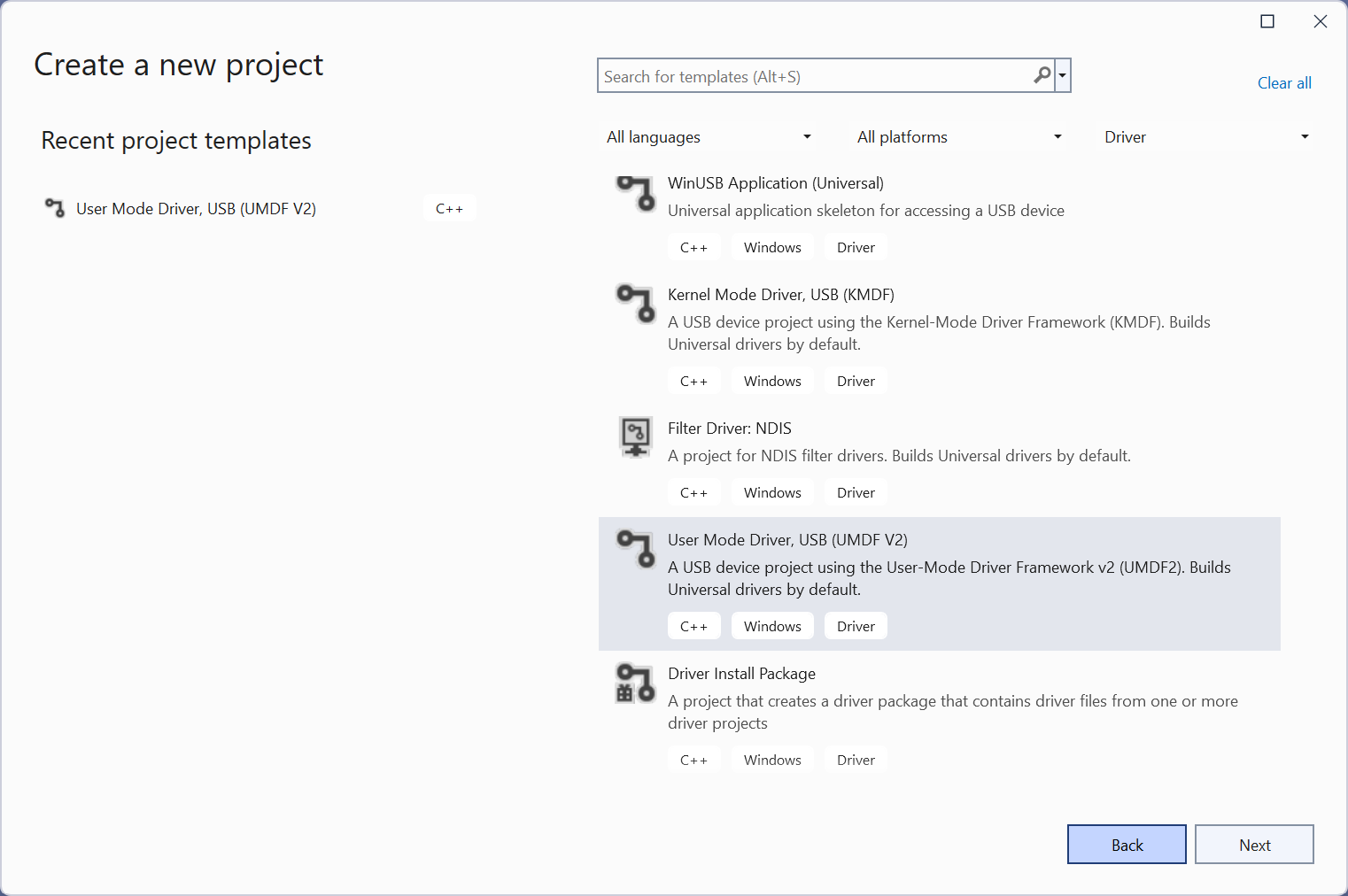
- In the New Project dialog box, in the search box at the top, type USB.
- In the middle pane, select User Mode Driver, USB (UMDF V2).
- Select Next.
- Enter a project name, choose a save location, and select Create.
The following screenshots show the New Project dialog box for the USB User-Mode Driver template.
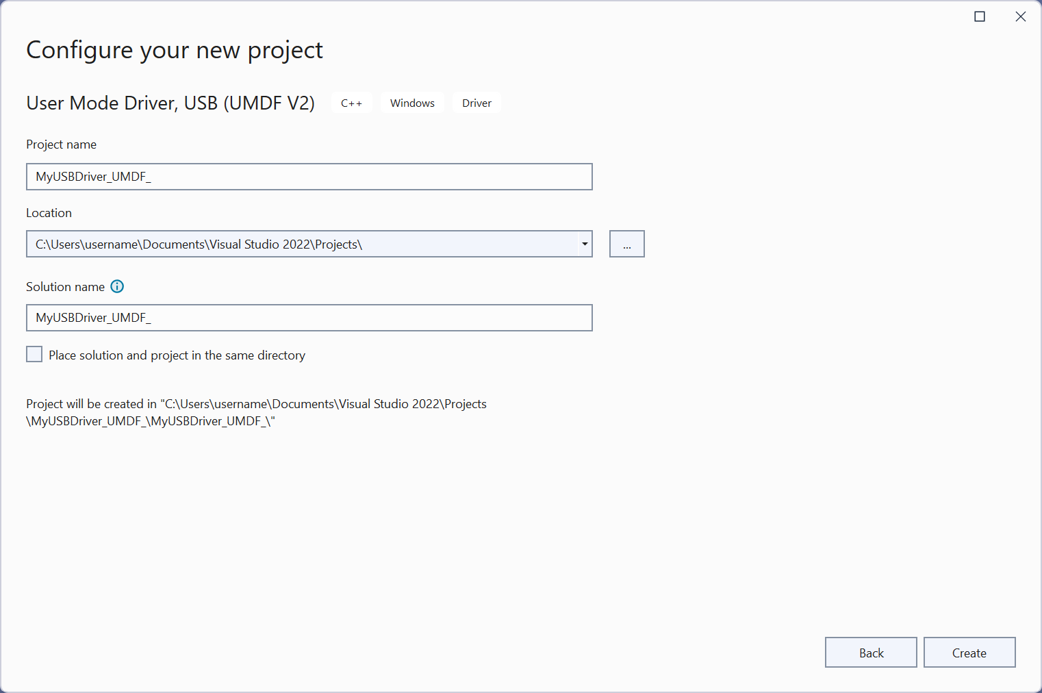
This article assumes that the name of the project is MyUSBDriver_UMDF_. It contains the following files:
| Files | Description |
|---|---|
| Driver.h; Driver.c | Contains the implementation of the driver module's entry point. DriverEntry and WDFDRIVER related functionality and callbacks. |
| Device.h; Device.c | WDFDEVICE and WDFUSBDEVICE related functionality and callbacks. |
| Queue.h; Queue.c | WDFQUEUE related functionality and callbacks. |
| Trace.h | Defines the device interface GUID. It also declares tracing functions and macros. |
| <Project name>.inf | INF file that is required to install the client driver on the target computer. |
Step 2: Add information about your device
Before you build the driver, you must add information about your device, specifically the hardware ID. To provide the hardware ID:
- In the Solution Explorer window, right-click MyUSBDriver_UMDF_, and choose Properties.
- In the MyUSBDriver_UMDF_ Property Pages window, go to Configuration Properties > Driver Install > Deployment, as shown here.
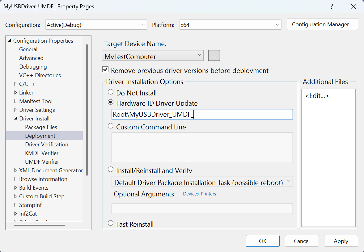
- Check Remove previous driver versions before deployment.
- For Target Device Name, select the name of the computer that you configured for testing and debugging.
- Select Hardware ID Driver Update, and enter the hardware ID for your driver. In this exercise, the hardware ID is Root\MyUSBDriver_UMDF_. Select OK.
Note
In this exercise, the hardware ID does not identify a real piece of hardware. It identifies an imaginary device that will be given a place in the device tree as a child of the root node. For real hardware, do not select Hardware ID Driver Update. Instead, select Install and Verify. You can see the hardware ID in your driver's information (INF) file. In the Solution Explorer window, go to MyUSBDriver_UMDF_ > Driver Files, and double-click MyUSBDriver_UMDF_.inf. The hardware ID is under [Standard.NT$ARCH$].
All UMDF-based USB client drivers require two Microsoft-provided drivers, the reflector and WinUSB.
Reflector: If your driver gets loaded successfully, the reflector is loaded as the top-most driver in the kernel-mode stack. The reflector must be the top driver in the kernel mode stack. To meet this requirement, the template's INF file specifies the reflector as a service and WinUSB as a lower-filter driver in the INF:
[MyDevice_Install.NT.Services] AddService=WUDFRd,0x000001fa,WUDFRD_ServiceInstall ; flag 0x2 sets this as the service for the device AddService=WinUsb,0x000001f8,WinUsb_ServiceInstall ; this service is installed because its a filter.WinUSB: The installation package must contain coinstallers for Winusb.sys because for the client driver, WinUSB is the gateway to the kernel-mode USB driver stack. Another component that gets loaded is a user-mode DLL, named WinUsb.dll, in the client driver's host process (Wudfhost.exe). Winusb.dll exposes WinUSB Functions that simplify the communication process between the client driver and WinUSB.
Step 3: Build the USB client driver code
To build your driver:
- Open the driver project or solution in Visual Studio 2022.
- Right-click the solution in the Solution Explorer and select Configuration Manager.
- From the Configuration Manager, select your Active Solution Configuration (for example, Debug or Release) and your Active Solution Platform (for example, x64) that correspond to the type of build you're interested in.
- Verify that your device interface GUID is accurate throughout the project.
- The device interface GUID is defined in Trace.h and is referenced from
MyUSBDriverUMDFCreateDevicein Device.c. When you create your project with the name MyUSBDriver_UMDF_, Visual Studio 2022 defines the device interface GUID with the nameGUID_DEVINTERFACE_MyUSBDriver_UMDF_but callsWdfDeviceCreateDeviceInterfacewith the incorrect parameter&GUID_DEVINTERFACE_MyUSBDriverUMDF. Replace the incorrect parameter with the name defined in Trace.h to ensure that the driver builds properly.
- The device interface GUID is defined in Trace.h and is referenced from
- From the Build menu, select Build Solution.
For more information, see Building a Driver.
Step 4: Configure a computer for testing and debugging
To test and debug a driver, you run the debugger on the host computer and the driver on the target computer. So far, you have used Visual Studio on the host computer to build a driver. Next you need to configure a target computer. To configure a target computer, follow the instructions in Provision a computer for driver deployment and testing.
Step 5: Enable tracing for kernel debugging
The template code contains several trace messages (TraceEvents) that can help you track function calls. All functions in the source code contain trace messages that mark the entry and exit of a routine. For errors, the trace message contains the error code and a meaningful string. Because WPP tracing is enabled for your driver project, the PDB symbol file created during the build process contains trace message formatting instructions. If you configure the host and target computers for WPP tracing, your driver can send trace messages to a file or the debugger.
To configure your host computer for WPP tracing
Create trace message format (TMF) files by extracting trace message formatting instructions from the PDB symbol file.
You can use Tracepdb.exe to create TMF files. The tool is located in the <install folder>Windows Kits\10\bin\<architecture> folder of the WDK. The following command creates TMF files for the driver project.
tracepdb -f <PDBFiles> -p <TMFDirectory>The -f option specifies the location and the name of the PDB symbol file. The -p option specifies the location for the TMF files that are created by Tracepdb. For more information, see Tracepdb Commands.
There are three files at the specified location, one per C code file in the project. They're given GUID file names.
In the debugger, type the following commands:
.load Wmitrace
.chain
!wmitrace.searchpath + <TMF file location>
These commands:
- Load the Wmitrace.dll extension.
- Verifies that the debugger extension is loaded.
- Adds the location of the TMF files to the debugger extension's search path.
The output resembles this:
Trace Format search path is: 'C:\Program Files (x86)\Microsoft Visual Studio 14.0\Common7\IDE;c:\drivers\tmf
To configure your target computer for WPP tracing
Make sure you have the Tracelog tool on your target computer. The tool is located in the <install_folder>Windows Kits\10\Tools\<arch> folder of the WDK. For more information, see Tracelog Command Syntax.
Open a Command Window and run as administrator.
Type the following command:
tracelog -start MyTrace -guid \#c918ee71-68c7-4140-8f7d-c907abbcb05d -flag 0xFFFF -level 7-rt -kd
The command starts a trace session named MyTrace.
The guid argument specifies the GUID of the trace provider, which is the client driver. You can get the GUID from Trace.h in the Visual Studio 2022 project. As another option, you can type the following command and specify the GUID in a .guid file. The file contains the GUID in hyphen format:
tracelog -start MyTrace -guid c:\\drivers\\Provider.guid -flag 0xFFFF -level 7-rt -kd
You can stop the trace session by typing the following command:
tracelog -stop MyTrace
Step 6: Deploy the driver on the target computer
- In the Solution Explorer window, right-click the project name (MyUSBDriver_UMDF_), and choose Properties.
- In the left pane, navigate to Configuration Properties > Driver Install > Deployment.
- For Target Device Name, specify the name of the target computer.
- Select Install/Reinstall and Verify.
- Select Ok.
- On the Debug menu, choose Start Debugging, or press F5 on the keyboard.
Note
Do not specify the hardware ID of your device under Hardware ID Driver Update. The hardware ID must be specified only in your driver's information (INF) file.
Step 7: View the driver in Device Manager
Enter the following command to open Device Manager.
devmgmtVerify that Device Manager shows the following node.
USB Device
MyUSBDriver_UMDF_Device
Step 8: View the output in the debugger
Verify that trace messages appear in the Debugger Immediate Window on the host computer.
The output should be similar to the following:
[0]0744.05F0::00/00/0000-00:00:00.000 [MyUSBDriver_UMDF_]CMyDevice::OnPrepareHardware Entry
[0]0744.05F0::00/00/0000-00:00:00.000 [MyUSBDriver_UMDF_]CMyDevice::OnPrepareHardware Exit
[1]0744.05F0::00/00/0000-00:00:00.000 [MyUSBDriver_UMDF_]CMyDevice::CreateInstanceAndInitialize Entry
[1]0744.05F0::00/00/0000-00:00:00.000 [MyUSBDriver_UMDF_]CMyDevice::Initialize Entry
[1]0744.05F0::00/00/0000-00:00:00.000 [MyUSBDriver_UMDF_]CMyDevice::Initialize Exit
[1]0744.05F0::00/00/0000-00:00:00.000 [MyUSBDriver_UMDF_]CMyDevice::CreateInstanceAndInitialize Exit
[1]0744.05F0::00/00/0000-00:00:00.000 [MyUSBDriver_UMDF_]CMyDevice::Configure Entry
[1]0744.05F0::00/00/0000-00:00:00.000 [MyUSBDriver_UMDF_]CMyIoQueue::CreateInstanceAndInitialize Entry
[1]0744.05F0::00/00/0000-00:00:00.000 [MyUSBDriver_UMDF_]CMyIoQueue::Initialize Entry
[1]0744.05F0::00/00/0000-00:00:00.000 [MyUSBDriver_UMDF_]CMyIoQueue::Initialize Exit
[1]0744.05F0::00/00/0000-00:00:00.000 [MyUSBDriver_UMDF_]CMyIoQueue::CreateInstanceAndInitialize Exit
[1]0744.05F0::00/00/0000-00:00:00.000 [MyUSBDriver_UMDF_]CMyDevice::Configure Exit
Remarks
Let's take a look at how the framework and the client driver work together to interact with Windows and handle requests sent to the USB device. This illustration shows the modules loaded in the system for a UMDF -based USB client driver.
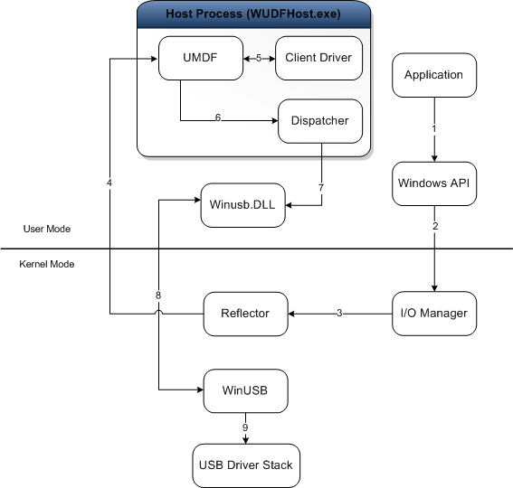
The purpose of each module is described here:
- Application — a user-mode process that issues I/O requests to communicate with the USB device.
- I/O Manager — a Windows component that creates I/O request packets (IRPs) to represent the received application requests, and forwards them to the top of the kernel-mode device stack for the target device.
- Reflector — a Microsoft-provided kernel-mode driver installed at the top of the kernel-mode device stack (WUDFRd.sys). The reflector redirects IRPs received from the I/O manager to the client driver host process. Upon receiving the request, the framework and the client driver handle the request.
- Host process — the process in which the user-mode driver runs (Wudfhost.exe). It also hosts the framework and the I/O dispatcher.
- Client driver — the user-mode function driver for the USB device.
- UMDF — the framework module that handles most interactions with Windows on the behalf of the client driver. It exposes the user-mode device driver interfaces (DDIs) that the client driver can use to perform common driver tasks.
- Dispatcher—mechanism that runs in the host process; determines how to forward a request to the kernel mode after it has been processed by user-mode drivers and has reached the bottom of the user-mode stack. In the illustration, the dispatcher forwards the request to the user-mode DLL, Winusb.dll.
- Winusb.dll — a Microsoft-provided user-mode DLL that exposes WinUSB Functions that simplify the communication process between the client driver and WinUSB (Winusb.sys, loaded in kernel mode).
- Winusb.sys — a Microsoft-provided driver that is required by all UMDF client drivers for USB devices. The driver must be installed below the reflector and acts as the gateway to the USB driver stack in the kernel-mode. For more information, see WinUSB.
- USB driver stack — a set of drivers, provided by Microsoft, that handle protocol-level communication with the USB device. For more information, see USB host-side drivers in Windows.
Whenever an application makes a request for the USB driver stack, the Windows I/O manager sends the request to the reflector, which directs it to client driver in user mode. The client driver handles the request by calling specific UMDF methods, which internally call WinUSB Functions to send the request to WinUSB. Upon receiving the request, WinUSB either processes the request or forwards it to the USB driver stack.
Related topics
Palaute
Tulossa pian: Vuoden 2024 aikana poistamme asteittain GitHub Issuesin käytöstä sisällön palautemekanismina ja korvaamme sen uudella palautejärjestelmällä. Lisätietoja on täällä: https://aka.ms/ContentUserFeedback.
Lähetä ja näytä palaute kohteelle