Visual Studio Code extension for Azure Video Analyzer
Note
Azure Video Analyzer has been retired and is no longer available.
Azure Video Analyzer for Media is not affected by this retirement. It is now rebranded to Azure Video Indexer. Click here to read more.
Azure Video Analyzer is a platform to make building video analysis programs easier, and the associated Visual Studio Code extension is a tool to make learning that platform easier. This article is a reference to the various pieces of functionality offered by the extension. It covers the basics of:
- Pipelines topologies – creation, editing, deletion, viewing the JSON
- Live pipelines – creation, activation, deactivation, deletion, viewing the JSON
- Editing a pipeline topology – modules, parameters, system variables, connections, validation
If you have not set up the extension to connect to your edge device, follow the steps in Use the Visual Studio Code extension for Azure Video Analyzer.
Managing pipelines topology
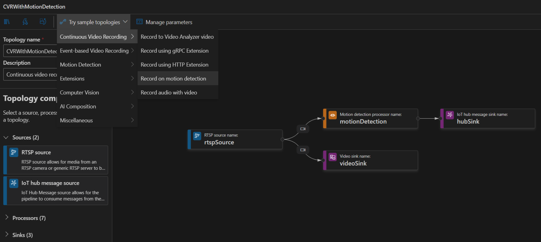
To create a topology, along the left panel under the Video Analyzer Edge module, right-click on Pipelines topologies and select Create pipeline topology. This will open up a new blank topology. Either load one of the pre-made topologies by selecting from the Try sample topologies dropdown at the top, or build one by dragging and dropping the available modules and connecting them.
After all required areas are complete, save the topology with the Save in the top right. For sample topologies, the required fields should be pre-filled. This will make it available for use with creating live pipelines.
To edit an existing topology, on the left panel under Pipeline topologies right-click on the name of the topology, and select Edit pipeline topology.
To delete an existing topology, on the left under Pipeline topologies right-click on the name of the topology, and select Delete pipeline topology. Live pipelines will need to be removed first.
To view the underlying JSON behind an existing topology, on the left panel under Pipeline topologies right-click on the name of the topology, and select Show pipeline topology JSON.
Live pipelines
To create a live pipeline, along the left panel under Pipeline topologies right-click on the name of the topology and select Create live pipeline. Fill in a live pipeline name and any required parameters before continuing. In the top right, either click Save which will save it in an inactive state, or Save and activate which will start the live pipeline immediately.
To activate an existing live pipeline, along the left panel under Pipeline topologies right-click on the name of the live pipeline and select Activate live pipeline.
To deactivate a running instance, along the left panel under Pipeline topologies right-click on the live pipeline and select Deactivate live pipeline. This will not delete the live pipeline.
To delete an existing live pipeline, along the left panel under Pipeline topologies right-click on the live pipeline and select Delete live pipeline. Active live pipelines cannot be deleted.
To view the underlying JSON behind an existing live pipeline, on the left panel under Pipeline topologies right-click on the live pipeline and select Show live pipeline JSON.
Remote device adapters
To create a remote device adapter, along the left panel under the Video Analyzer Edge module, right-click on Remote device adapters and select Create remote device adapter. Three additional dialog boxes appear, prompting for additional information:
- Enter a unique name for the remote device adapter. (There should be no other remote device adapters with this name.)
- Select a IoT Device. (For instance, select the IoT device that represents the network camera that will be connected.)
- Enter a hostname or IP address of the remote device adapter. (For instance, enter the IP address of the network camera that will be connected.)
After entering all the necessary information, the remote device adapter will be saved and listed under the Remote device adapters section.
To delete an existing remote device adapter, along the left panel under Remote device adapters right-click on a remote device adapter and select Delete remote device adapter.
To view the underlying JSON behind an existing remote device adapter, along the left panel under Remote device adapters right-click on a remote device adapter and select Show remote device adapter JSON.
Editing a topology
Pipeline topologies are constructed of a variety of pieces. You can learn about these pieces in the Pipelines concept doc. This section is about the portions of the interface to help you build or edit a topology.
Modules
Modules are available along the left, and are grouped into sources, processors, and sinks. To add one to your topology drag it in to the editing area.
If you want another module of the same type with the same starting parameters, you can duplicate it by right-clicking on the module and selecting Copy.
If you want to remove a module from the topology, right-click on the module and select Delete.
Parameters
You can edit the attributes on a module by left clicking on it in the editing area. This will bring up a pane on the right with a list of all the elements. Required items are marked with a red asterisk. There is a brief description in the information text by the name of each item.
As topologies are effectively templates that you may make multiple live pipelines from, some items you will want to fill in at creation time. You can do this with parameters. To activate this, right-click on the three dots along the right of the attribute and select Parameterize. This will bring up a window.
In the parameterization window, you can create a new parameter which will work as a value you fill in at live pipeline creation, or select from an existing one. Creating a new one requires you to fill out the name and type. You can optionally enter a default value if this will only sometimes need to be changed. When a live pipeline is created only parameters without a default value will be required. When you are done, click Set.
If you wish to manage your existing parameters, this can be done with the Manage parameters option along the top. The pane that comes allows you to add new parameters, and either edit or delete existing ones.
System variable
When creating a series of live pipelines, there are likely cases where you want to use variables to help name files or outputs. For example, you may wish to name a video clip with the live pipeline name and date / time so you know where it came from and at what time. Video Analyzer provides three system variables you can use in your modules to help here.
| System Variable | Description | Example |
|---|---|---|
| System.Runtime.DateTime | UTC date time in ISO8601 file compliant format (basic representation YYYYMMDDThhmmss). | 20200222T173200Z |
| System.TopologyName | User provided name of the executing pipeline topology. | IngestAndRecord |
| System.PipelineName | User provided name of the executing live pipeline. | camera001 |
Connections
When you create a topology, you will need to connect the various modules together. This is done with connections. From the circle on the edge of a module, drag to the circle on the next module you want data to flow to. This will produce a connection.
By default, connections send video data from one module to another. If you want to send only audio data or application data, you can left click on the connection and edit the output types. Selectable types of data include video, audio, and application. Selecting none of the output types will be treated as sending all applicable data from the sender node.
Sample pipeline topologies
The following sample pipeline topologies are available on the extension:
Continuous Video Recording
Record to Video Analyzer video

Record using gRPC Extension

Record using HTTP Extension

Record on motion detection
Record audio with video

Event-based Video Recording
Record using gRPC Extension

Record using HTTP Extension

Record to Video Analyzer video based on inference events

Record to local files based on inference events

Record motion events to Video Analyzer video and local files

Record motion events to Video Analyzer video

Record motion events to local files

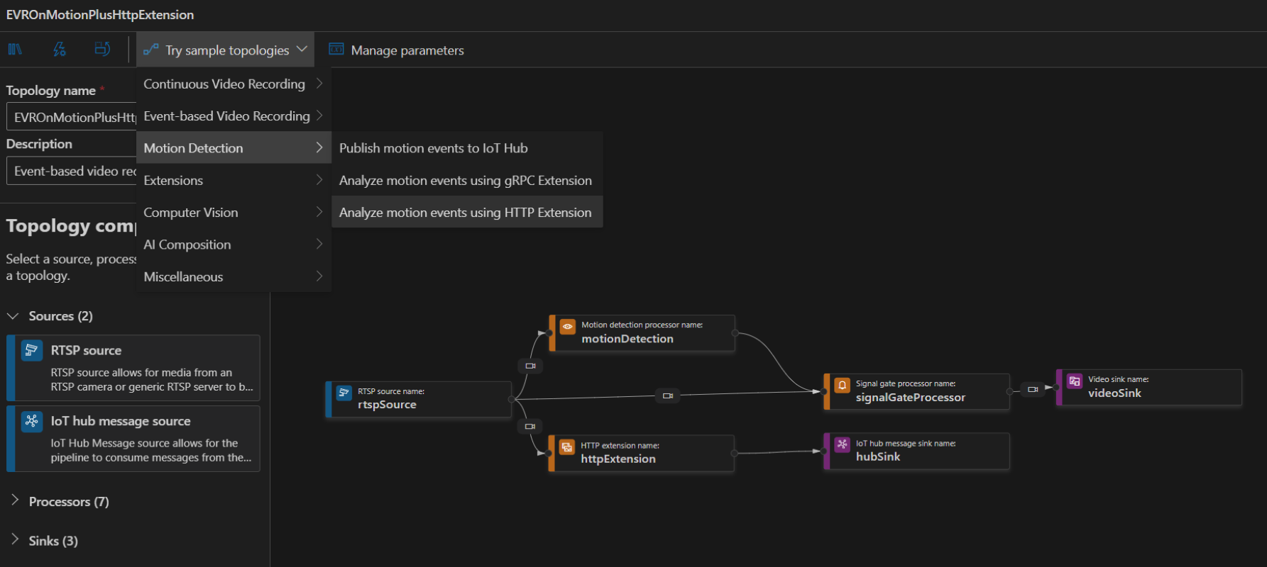
Motion Detection
Publish motion events to IoT Hub

Analyze motion events using gRPC Extension

Analyze motion events using HTTP Extension
Extensions
Analyze video using HTTP Extension

Analyze video with Intel OpenVINO Model Server

Computer Vision
Person count operation with Computer Vision for Spatial Analysis

Person crossing line operation with Computer Vision for Spatial Analysis

Person crossing zone operation with Computer Vision for Spatial Analysis

Person distance operation with Computer Vision for Spatial Analysis
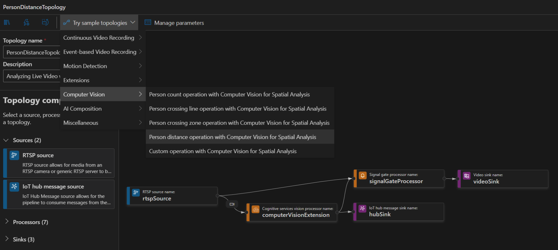
Custom operation with Computer Vision for Spatial Analysis

AI Composition
Record to the Video Analyzer service using multiple AI models

Miscellaneous
Record video based on the object tracking AI model
![]()
Record video based on the line crossing AI model
