RF tools
The Radio Frequency (RF) tools enable low-level control of the radio, as required during design verification and manufacturing of hardware based on Azure Sphere. The tools include interactive applications for control and display of the RF settings.
If you are designing a board or module that incorporates an MT3620 chip, you must test and calibrate the radio before you ship the board or module. If you are manufacturing a connected device that includes a board or module from another supplier, the supplier should already have performed RF testing; check with your supplier if you have any questions.
Manufacturing connected devices includes information on how RF testing fits into the manufacturing workflow.
Important
The RF tools require the Enable RF test mode capability. This capability is present by default on boards that are in the Blank manufacturing state, but is not available in the Module1Complete or DeviceComplete state.
Use the az sphere device capability show-attached command to determine whether this capability is present on your device. If you need to run the RF tools on a device that does not have this capability, follow the instructions in Request the RF tools to contact Microsoft for assistance.
The RF tools use only the Service UART port which must be connected to a USB port on your PC. The RF tools require that the UART be exposed by the Future Technology Devices International (FTDI) FT4232HQ UART-to-USB interface chip. For details about the Service UART port, see MCU programming and debugging interface.
Request the RF tools
Microsoft supplies the RF Tools package upon request to customers, partners, and security researchers. You can request them from your technical sales professional (TSP). If you don't have a TSP, please send an email to azcommunity@microsoft.com with the following information:
Your name, organization, and contact information.
Contact information for your Microsoft account team or TSP, if you have one.
If you're building a module (rather than a device that uses MT3620 chips directly), your reason for requiring the RF tools.
The kinds of tests you plan to run using the tools.
Projected timeline for manufacturing (when do devices need to be manufactured/certified).
A Microsoft representative will work with you to determine the appropriate distribution channel.
Setup and installation
Before you can run the RF tools, you must set up your PC and your MT3620 device with the latest software and unzip the tools, as described in the following sections.
PC setup
Set up your PC with the current Azure Sphere SDK.
MT3620 device setup
After you set up your PC, make sure that your MT3620 device is running the most recent Azure Sphere OS. Follow the instructions in the Release Notes for the current release.
RF tool installation
Unzip the RF Tools Package into a directory on your PC. The resulting folder contains three subfolders:
Configurations, which contains files to facilitate radio configuration settings
Libraries, which contains the C libraries for performing RF testing
RfToolCli, which contains the interactive command-line RfToolCli and the read-only RfSettingsTool
MT3620 RF configuration and calibration
The MT3620 stores radio configuration and calibration data in e-fuses, which can be programmed a limited number of times. This data includes the radio bands (such as 2.4GHz or 5GHz) that the chip should support, adjustments to transmit power, and the antenna configuration on the device. For detailed information about e-fuse configuration, see the MT3620 N9 E-fuse content guidelines, which are available from MediaTek.
Antenna diversity
Radio signals bounce off objects in the environment. As a result, a single radio signal takes multiple paths from transmitter to receiver. Because these radio signals travel different distances, they arrive at the receiver at different times. Occasionally, the arriving signals interfere destructively and the antenna does not see any signal. One way to address this problem is through antenna diversity. To provide antenna diversity, a second antenna that has a different orientation is placed a short distance (at least a quarter wavelength) away from the first.
The MT3620 supports two antenna diversity configurations, which are configured using radio e-fuses. The figure shows the two configurations.
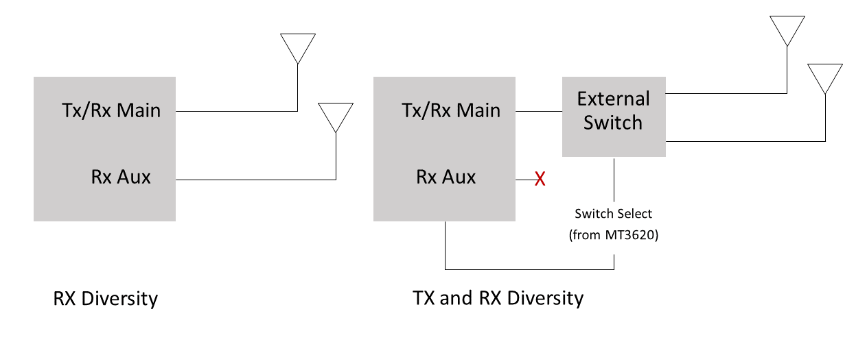
The configuration on the left shows receive diversity (RX diversity). In this configuration, a second antenna is attached to the auxiliary antenna port. If the received signal level on the main antenna port drops below a certain threshold, the MT3620 automatically switches to the second antenna when receiving data. In this configuration, transmissions must still use the primary antenna.
The configuration on the right shows transmit and receive diversity (TX and RX diversity), uses the secondary antenna to both transmit and receive. The MT3620 achieves this through the use of an external double-pole, double-throw (DPDT) switch, which allows the signal to be routed to either antenna. In the transmit and receive diversity configuration, the auxiliary antenna port is unused. The MT3620 has two dedicated antenna selection pins for controlling this external switch.
Buffer bins
During RF testing, the MT3620 can use values in volatile memory instead of the permanent e-fuses, so that test operators and equipment can adjust these settings without permanently changing the e-fuses. The volatile memory used to store these settings is referred to as the "buffer bin." After the test operator or equipment is sure that the values in the buffer bin are correct, the state of the buffer bin can be permanently written to e-fuses.
When entering RF test mode, it is possible to set the contents of the buffer bin to known, pre-set values by loading a "default buffer bin" file. The test operator or equipment can then set additional configuration or calibration values as necessary.
The RF Tools package provides several default buffer bin files in the Configurations\MT3620 directory. These files can be used to initialize the device to a pre-configured state or to override any calibration settings that have previously been programmed into the permanent e-fuses on the device under test (DUT).
The following buffer bin files support transmission with the main antenna:
MT3620_eFuse_N9_V5_20180321_24G_5G_NoDpdt.bin sets the radio to support both 2.4GHz and 5GHz operation.
MT3620_eFuse_N9_V5_20180321_24G_Only_NoDpdt.bin sets the radio to support 2.4GHz operation only.
The following buffer bin files support transmitting with an auxiliary antenna:
MT3620_eFuse_N9_V5_20180321_24G_5G_Dpdt.bin supports 2.4GHz and 5GHz operation with the DPDT switch.
MT3620_eFuse_N9_V5_20180321_24G_Only_Dpdt.bin supports 2.4GHz operation with the DPDT switch.
Default buffer bin files can be further customized to your specific device application. Please contact MediaTek or Microsoft for other customization options.
After completion of RF Tools usage
After the RF testing and calibration have been completed on a manufactured device, the rftest_server.imagepackage should be removed from the device and the manufacturing state of the device should be set to prevent further RF settings modifications.
Removal of rftest_server.imagepackage
After using the RF Tools, a package named rftest_server.imagepackage may be left on the device. This OS package enables access over the FTDI interface to the low-level RF configuration. This package is automatically removed by AS3 when the device next connects to AS3. However, manufacturers using the RF Tools should delete this package when RF testing is complete.
To delete the package:
Run the az sphere device image command as follows:
az sphere device image list-installed --fullCheck whether there is a component installed named rftest_server. If so, then run the az sphere device sideload command followed by the az sphere device image command as follows:
az sphere device sideload delete -component-id <component ID of rftest_server>The device will reboot after running this command.
az sphere device image list-installed --fullObserve that the rftest_server imagepackage is no longer present after running this command.
Prevent further RF settings modification
In order to prevent further RF settings modifications, you should set the manufacturing state of the device as Module1Complete.
Note that if the device immediately moves on to having the application loaded (for example, a chip-down design where RF testing and device software loading are done on a single production line), then this step can be skipped. At the end of the application loading and testing process, the device is moved into DeviceComplete state which also prevents RF settings modification.
RfToolCli
RfToolCli is an interactive command-line tool that allows low-level control of the MT3620 radio for testing and diagnostic purposes. Before you run this tool, ensure that the device under test (DUT) is connected and is running the latest Azure Sphere OS.
To use the tool, open a Command Prompt window, go to the directory that contains RfToolCli.exe, and run RfToolCli. The command has two start-up options:
rftoolcli [-BufferBin <filename>] [-Image <filename>]
The -BufferBin option passes the path to a custom default buffer-bin configuration file. By default, RfToolCli uses radio settings that are programmed onto the device. These settings include any transmit power adjustments, allowed frequency bands, and antenna configurations. To use an alternative settings file, supply the path to the file with the -BufferBin option.
The -Image option passes the path to the rftest-server.imagepackage file. This image package file must be loaded onto the DUT to put the device into RF test mode. The rftest-server is provided in the same folder as the RfToolCli executable and in most circumstances RfToolCli can locate this file. If you are running RfToolCli from a different location, you might need to use the -Image option to pass the path to this file.
At startup, RfToolCli prepares the device and then displays an interactive prompt:
C:\Rf\RfToolCli> .\RfToolCli.exe
Preparing DUT...
>
RFToolCli provides the commands listed in the following table.
| Command (abbreviation) options | Description |
|---|---|
| antenna {aux | main} | Selects the auxiliary or main antenna. |
| channel number | Selects a channel. |
| config read {macaddress | data} |
Gets device MAC address and buffer bin data. |
| config write {macaddress | data} |
Sets device MAC address and buffer bin data. |
| config save | Saves changes to MAC address or buffer bin data to permanent e-fuses. |
| exit | Exits from the program. |
| help command-name | Displays help on a command. |
| receive (rx) {start | stop | stats} |
Starts or stops receiving, or displays statistics about received packets. |
| settings | Displays current radio settings. |
| showchannel (sc) | Lists the channels that the device supports. |
| transmit (tx) {frame | mode | power | rate | start} | Configures and transmits packets. The frame, mode, power, and rate options configure the packets; each has parameters that define the relevant configuration setting. The start option starts transmission. |
You can get help for any command by typing help followed by the command name and, if applicable, an option. For example:
help transmit frame
Usage:
Transmit Frame [-BSS <Str>] [-Destination <Str>] [-Duration
<UInt16>]
[-FrameControl <UInt16>] [-Source <Str>]
Configure transmit frame header
Optional Parameters:
-BSS <Str> - BSS MAC address (in colon-delimited format)
-Destination <Str> - Destination MAC address (in colon-delimited
format)
-Duration <UInt16> - Frame duration [Alias: -D]
-FrameControl <UInt16> - Frame Control Number [Alias: -F]
-Source <Str> - Source MAC address (in colon-delimited format)
Example: View start-up settings
At startup, RfToolCli sets several defaults including transmit modes, data rate and channel. To view these startup settings, use the settings command.
 > settings
 ------Radio------

 Mode: Normal
 Power: 16.0
 Channel: 1
 Rate: Ofdm54M

---TX Frame Header---

Frame Control: 8000
Duration: 2000
BSS MAC: 62:45:8D:72:06:18
Source MAC: AC:AC:AC:AC:AC:AC
Destination MAC: 62:45:8D:72:06:18

---TX Frame Data---

Frame Size: 1000
Use Random Data: True
Example: Set channel and get received packet statistics
This command sequence puts the radio into receive mode on the specified 802.11 channel and then gets statistics about the packets received:
> channel 9
Setting channel to 9
> rx start
Starting receive
> rx stats
Total packets received: 2578
Data packets received: 4
Unicast packets received: 0
Other packets received: 4
>
Example: Transmit packets on current channel
This command causes the radio to transmit packets on the current channel:
> transmit start
Starting transmit
Press any key to stop transmission
Example: Transmit packets in continuous mode on current channel
This command causes the radio to transmit packets on the current channel in continuous mode until you stop transmission or set a different the mode:
> tx mode continuous
> tx start
Starting transmit
Press any key to stop transmission
When the device transmits in continuous mode, there is no gap between packets, which is useful for power measurements.
Example: Transmit a continuous tone on the current channel
This command sequence causes the radio to transmit a tone on the current channel until you press a key.
> tx continuouswave
> tx start
Starting transmit
Press any key to stop transmission
Example: Get the device's currently configured MAC address
This command reads the currently configured MAC address on the device.
> config read MacAddress
Device MAC address: 4E:FB:C4:1C:4F:0C
Example: Set the device's MAC address
This command writes a new MAC address to the device's buffer bin. If a MAC address is already set for the device, you will be asked to confirm the change.
> config write MacAddress 02:12:ab:cd:ef:11
Device already has MAC address 4E:FB:C4:1C:4F:0C
Are you sure you want to modify this? (y/N):y
Note
To make buffer bin or MAC addresses changes permanent, use the config save command.
Example: Set one byte of configuration data
The config write data command can be used to set one byte of data at the specified buffer bin address.
> config write data 0x34 0xDD
Example: Display device configuration data
The config read data command outputs the entire contents of the device buffer bin.
> config read data
Current configuration data:
0x0000: 20 36 04 00 B2 EE D2 16 E5 73 00 00 00 00 00 00
0x0010: 00 00 00 00 00 00 00 00 00 00 00 00 00 00 00 00
0x0020: 00 00 00 00 00 00 00 00 00 00 00 00 00 00 00 00
0x0030: 00 00 00 00 00 00 00 00 FF FF 20 00 60 00 CC 00
...
Example: Save configuration data to e-fuses
The config save command permanently writes any changes to the buffer bin to the non-volatile e-fuses. The e-fuses can only be written a limited number of times, so we strongly recommend that you perform all buffer bin changes first and then write these changes to e-fuses in a single step.
> config save
About to commit data to non-volatile storage
Changes will be permanent. Continue? (y/N):y
Done
RF settings tool
The RF settings tool displays MT3620 e-fuse settings so that you can validate that they have been set correctly. Unlike RfToolCli, the RF settings tool is read-only. Therefore, it can be used to inspect device settings even after radio testing functionality has been disabled on a particular device.
To use the tool, open a Command Prompt window, go to the RfToolCli folder, and run RfSettingsTool. The tool has two commands and has two start-up options:
rfsettingstool <command> [--image <filename>] [--usefile <filename>]
The following commands are supported:
| Command (abbreviation) | Description |
|---|---|
| check (c) | Validates MT3620 device configuration data |
| help (?) | Shows help information |
| show (s) | Shows MT3620 configuration data. |
RfSettingsTool check command
The RfSettingsTool check command reads the configuration from the attached device and compares it against a buffer bin configuration file that contains the expected settings. The check command has the following format:
rfSettingsTool.exe check --expected <filename> [--image <filename>] [--nomacaddress] [--showconfig] [--usefile <filename>] [--verbose]
| Parameters (abbreviation) | Description |
|---|---|
| --expected filename (-e) | Path to the buffer bin file that contains the expected e-fuse settings to check against. Required. |
| --image filename (-i) | Path to RF test image. If omitted, defaults to rftest-server.imagepackage. Optional. |
| --nomacaddress (-n) | Indicates that no MAC address should be set on the device. Optional. |
| --showconfig (-s) | Shows device configuration after check. Optional. |
| --usefile filename (-u) | Reads configuration data from the specified file instead of the attached device. Optional. |
| --verbose (-v) | Shows extra output information. |
For example, the following command verifies that the radio setting match those in the specified buffer bin file:
> RfSettingsTool.exe check --expected ..\Configurations\MT3620\
MT3620_eFuse_N9_V5_20180321_24G_5G_DPDT.bin
In response to this command, RfSettingsTool checks the following items. All must be true for the command to succeed:
Region code is identical to expected setting
External antenna switch present identical to expected setting
Antenna configuration identical to expected setting
Target power identical to expected setting
Operating bands identical to expected setting
MAC address has been set
Radio power offsets, which are device-specific, are not checked.
RfSettingsTool show command
The RfSettingsTool show command displays the radio settings that have been set on the MT3620 e-fuses in a human-readable way. The fields displayed are the user-configurable radio settings.The check command has the following format:
rfSettingsTool.exe show [--hexdump] [--image <filename>] [--usefile <filename>] [--verbose]
| Parameters (abbreviation) | Description |
|---|---|
| --hexdump (-x) | Shows the raw hexadecimal contents of e-fuses. Optional. |
| --image filename (-i) | Path to RF test image. If omitted, defaults to rftest-server.imagepackage. Optional. |
| --usefile filename (-u) | Reads configuration data from the specified file instead of the attached device. Optional. |
| --verbose (-v) | Shows extra output information. |
The following example shows partial output from the show command:
> RfSettingsTool.exe show
Reading configuration data from device.
--------------------------------------------------------------------------------
MAC Address : C6:76:EC:79:1D:6B
--------------------------------------------------------------------------------
Region : GB
--------------------------------------------------------------------------------
External RF switch : Present
2.4GHz Diversity : MainOnly
5GHz Diversity : MainOnly
.
.
.
RF test C library
The RF Tools package includes a C library that you can use to develop your own test programs. The C library is in the libraries\C directory. Header files for the C API are available in the libraries\C\Include folder, and binary files that are required to use the library are provided in the libraries\C\Bin folder. If you want to use the library, please contact Microsoft for documentation.
The RF testing server image (rftest-server.imagepackage) is also provided in the Bin folder. This image must be loaded on the device under test before the device can enter RF testing mode. The mt3620rf_load_rf_test_server_image() function in the C library loads the image package programmatically.
If you redistribute an application that uses the C library, you must include the DLL files from libraries\C\Bin as well as the rftest-server.imagepackage file.
Compatibility of RF tools across OS versions
There is no guarantee that RF tools for one OS release will be compatible across all OS versions. Generally, we recommend that you use the version of the tools (and associated C Library) that is issued with the manufacturing package for the OS running on the device under test.
The following table summarizes the compatibility of tool releases with Azure Sphere OS releases.
| RF Tools Release | OS Release |
|---|---|
| 21.01 | 21.01 and later |
| 20.10 | 20.07 or 20.10 |
| 20.07 | 20.07 |
| 20.04 | 20.04 or 20.01 |
| 20.01 | 20.04 or 20.01 |
See What's new in Azure Sphere to learn about any additional changes in the current release.
Errata
The following errata apply to all versions of the RF tools on MT3620 hardware. Additional release-specific problems are listed in the README file that is part of the tools package.
The MT3620 Wi-Fi firmware has a minor bug:
If you switch to Continuous mode transmission (tx mode continuous) and start transmission (tx start) immediately after stopping a Normal mode transmission, there will be no signal output.
To work around this, stop the Continuous mode transmission and start it again for the transmission to commence. After this, Continuous mode transmission will work correctly.
The problem does not occur when switching from Continuous Mode to Normal mode.
When switching from Continuous Wave transmission mode to Normal or Continuous transmission modes, transmit power will incorrectly increase by +6 dB. You must re-initialize the radio to return the power level to normal.
- If using the RfToolCli interactive tool, reinitialize the radio by exiting and then and restarting the tool.
- If using the C API, call the mt3620_reinitialize_buffer_bin() function. This will also reinitialize the radio and can be used to work around this problem.
Pripomienky
Pripravujeme: V priebehu roka 2024 postupne zrušíme službu Problémy v službe GitHub ako mechanizmus pripomienok týkajúcich sa obsahu a nahradíme ju novým systémom pripomienok. Ďalšie informácie nájdete na stránke: https://aka.ms/ContentUserFeedback.
Odoslať a zobraziť pripomienky pre