Create Shaders with Shader Designer in Visual Studio
In this article, you learn how to use the Shader Designer to create different kinds of shaders.
Create basic flat color shaders
You can use the Shader Designer and the Directed Graph Shader Language (DGSL) to create a flat color shader. This shader sets the final color to a constant RGB color value. You can implement a flat color shader by writing the color value of an RGB color constant to the final output color.
Before you begin, make sure that the Properties window and the Toolbox are displayed.
Create a DGSL shader to work with. For information about how to add a DGSL shader to your project, see the Getting Started section in Shader Designer.
Delete the Point Color node. Use the Select tool to select the Point Color node, and then on the menu bar, choose Edit > Delete.
Add a Color Constant node to the graph. In the Toolbox, under Constants, select Color Constant and move it to the design surface.
Specify a color value for the Color Constant node. Use the Select tool to select the Color Constant node, and then, in the Properties window, in the Output property, specify a color value. For orange, specify a value of (1.0, 0.5, 0.2, 1.0).
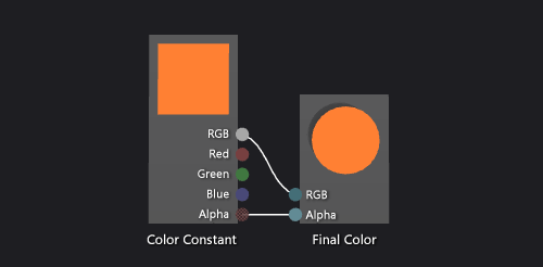
Connect the color constant to the final color. To create the connections, move the RGB terminal of the Color Constant node to the RGB terminal of the Final Color node, and then move the Alpha terminal of the Color Constant node to the Alpha terminal of the Final Color node. These connections set the final color to the color constant defined in the previous step.
The following illustration shows the completed shader graph and a preview of the shader applied to a cube.
Note
In the illustration, an orange color was specified to better demonstrate the effect of the shader.
Certain shapes might provide better previews for some shaders. For more information about how to preview shaders in the Shader Designer, see Shader Designer.
Create basic Lambert shaders
You can also use the Shader Designer and the Directed Graph Shader Language (DGSL) to create a lighting shader that implements the classic Lambert lighting model.
The Lambert lighting model incorporates ambient and directional lighting to shade objects in a 3D scene. The ambient components provide a base level of illumination in the 3D scene. The directional components provide additional illumination from directional (far-away) light sources. Ambient illumination affects all surfaces in the scene equally, regardless of their orientation. For a given surface, it's a product of the ambient color of the surface and the color and intensity of ambient lighting in the scene. Directional lighting affects every surface in the scene differently, based on the orientation of the surface with respect to the direction of the light source. It's a product of the diffuse color and orientation of the surface, and the color, intensity, and direction of the light sources. Surfaces that face directly toward the light source receive the maximum contribution and surfaces that face directly away receive no contribution. Under the Lambert lighting model, the ambient component and one or more directional components are combined to determine the total diffuse color contribution for each point on the object.
Before you begin, make sure that the Properties window and the Toolbox are displayed.
Create a DGSL shader with which to work. For information about how to add a DGSL shader to your project, see the Getting Started section in Shader Designer.
Disconnect the Point Color node from the Final Color node. Choose the RGB terminal of the Point Color node, and then choose Break Links. Leave the Alpha terminal connected.
Add a Lambert node to the graph. In the Toolbox, under Utility, select Lambert and move it to the design surface. The lambert node computes the total diffuse color contribution of the pixel, based on ambient and diffuse lighting parameters.
Connect the Point Color node to the Lambert node. In Select mode, move the RGB terminal of the Point Color node to the Diffuse Color terminal of the Lambert node. This connection provides the lambert node with the interpolated diffuse color of the pixel.
Connect the computed color value to the final color. Move the Output terminal of the Lambert node to the RGB terminal of the Final Color node.
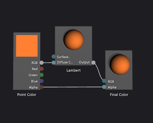
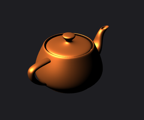
The following illustration shows the completed shader graph and a preview of the shader applied to a teapot model.
Note
To better demonstrate the effect of the shader in this illustration, an orange color has been specified by using the MaterialDiffuse parameter of the shader. A game or app can use this parameter to supply a unique color value for each object. For information about material parameters, see Shader Designer.
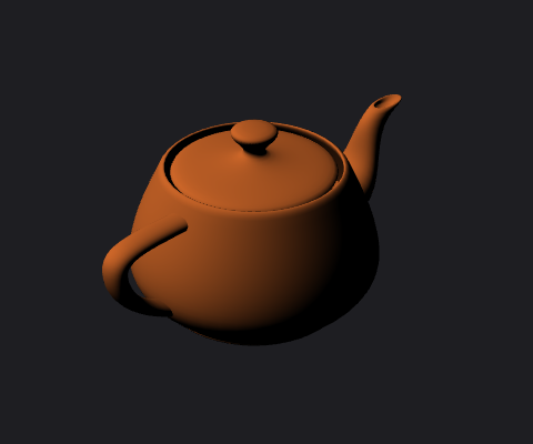
The following illustration shows the shader that's described in this document applied to a 3D model.
Create basic Phong shaders
You can also use the Shader Designer and the Directed Graph Shader Language (DGSL) to create a lighting shader that implements the classic Phong lighting model.
The Phong lighting model extends the Lambert lighting model to include specular highlighting, which simulates the reflective properties of a surface. The specular component provides additional illumination from the same directional light sources that are used in the Lambert lighting model, but its contribution to the final color is processed differently. Specular highlighting affects every surface in the scene differently, based on the relationship between the view direction, the direction of the light sources, and the orientation of the surface. It's a product of the specular color, specular power, and orientation of the surface, and the color, intensity, and direction of the light sources. Surfaces that reflect the light source directly at the viewer receive the maximum specular contribution and surfaces that reflect the light source away from the viewer receive no contribution. Under the Phong lighting model, one or more specular components are combined to determine the color and intensity of specular highlighting for each point on the object, and then are added to the result of the Lambert lighting model to produce the final color of the pixel.
For more information about the Lambert lighting model, see How to: Create a basic Lambert shader.
Before you begin, make sure that the Properties window and the Toolbox are displayed.
Create a Lambert shader, as described in How to: Create a basic Lambert shader.
Disconnect the Lambert node from the Final Color node. Choose the RGB terminal of the Lambert node, and then choose Break Links. This makes room for the node that's added in the next step.
Add an Add node to the graph. In the Toolbox, under Math, select Add and move it to the design surface.
Add a Specular node to the graph. In the Toolbox, under Utility, select Specular and move it to the design surface.
Add the specular contribution. Move the Output terminal of the Specular node to the X terminal of the Add node, and then move the Output terminal of the Lambert node to the Y terminal of the Add node. These connections combine the total diffuse and specular color contributions for the pixel.
Connect the computed color value to the final color. Move the Output terminal of the Add node to the RGB terminal of the Final Color node.
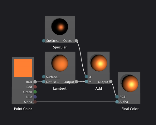
The following illustration shows the completed shader graph and a preview of the shader applied to a teapot model.
Note
To better demonstrate the effect of the shader in this illustration, an orange color has been specified by using the MaterialDiffuse parameter of the shader, and a metallic-looking finish has been specified by using the MaterialSpecular and MaterialSpecularPower parameters. For information about material parameters, see Shader Designer.
Certain shapes might provide better previews for some shaders. To learn more about previewing shaders, see Shader Designer.
The following illustration shows the shader that's described in this document applied to a 3D model. The MaterialSpecular property is set to (1.00, 0.50, 0.20, 0.00), and its MaterialSpecularPower property is set to 16.
Note
The MaterialSpecular property determines the apparent finish of the surface material. A high-gloss surface such as glass or plastic tends to have a specular color that is a bright shade of white. A metallic surface tends to have a specular color that is close to its diffuse color. A satin-finish surface tends to have a specular color that is a dark shade of gray.
The MaterialSpecularPower property determines how intense the specular highlights are. High specular powers simulate duller, more-localized highlights. Very low specular powers simulate intense, sweeping highlights that can oversaturate and conceal the color of the whole surface.
Create basic texture shaders
Use the Shader Designer and the Directed Graph Shader Language (DGSL) to create a single-texture shader. This shader sets the final color directly to the RGB and alpha values that are sampled from the texture.
You can implement a basic, single-texture shader by writing the color and alpha values of a texture sample directly to the final output color.
Before you begin, make sure that the Properties window and the Toolbox are displayed.
Create a DGSL shader to work with. For information about how to add a DGSL shader to your project, see the Getting Started section in Shader Designer.
Delete the Point Color node. In Select mode, select the Point Color node, and then on the menu bar, choose Edit > Delete. This makes room for the node that's added in the next step.
Add a Texture Sample node to the graph. In the Toolbox, under Texture, select Texture Sample and move it to the design surface.
Add a Texture Coordinate node to the graph. In the Toolbox, under Texture, select Texture Coordinate and move it to the design surface.
Choose a texture to apply. In Select mode, select the Texture Sample node, and then in the Properties window, specify the texture that you want to use by using the Filename property.
Make the texture publicly accessible. Select the Texture Sample node, and then in the Properties window, set the Access property to Public. Now you can set the texture from another tool, such as the Model Editor.
Connect the texture coordinates to the texture sample. In Select mode, move the Output terminal of the Texture Coordinate node to the UV terminal of the Texture Sample node. This connection samples the texture at the specified coordinates.
Connect the texture sample to the final color. Move the RGB terminal of the Texture Sample node to the RGB terminal of the Final Color node, and then move the Alpha terminal of the Texture Sample node to the Alpha terminal of the Final Color node.
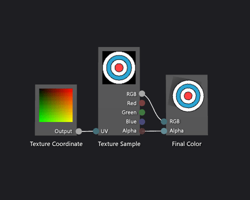
The following illustration shows the completed shader graph and a preview of the shader applied to a cube.
Note
In this illustration, a plane is used as the preview shape, and a texture has been specified to better demonstrate the effect of the shader.
Certain shapes might provide better previews for some shaders. For more information about how to preview shaders in the Shader Designer, see Shader Designer
Create grayscale texture shaders
Use the Shader Designer and the Directed Graph Shader Language (DGSL) to create a grayscale texture shader. This shader modifies the RGB color value of the texture sample, and then uses it together with the unmodified alpha value to set the final color.
You can implement a grayscale texture shader by modifying the color value of a texture sample before you write it to the final output color.
Before you begin, make sure that the Properties window and the Toolbox are displayed.
Create a basic texture shader, as described in How to: Create a basic texture shader.
Disconnect the RGB terminal of the Texture Sample node from the RGB terminal of the Final Color node. In Select mode, choose the RGB terminal of the Texture Sample node, and then choose Break Links. This makes room for the node that's added in the next step.
Add a Desaturate node to the graph. In the Toolbox, under Filters, select Desaturate and move it to the design surface.
Calculate the grayscale value by using the Desaturate node. In Select mode, move the RGB terminal of the Texture Sample node to the RGB terminal of the Desaturate node.
Note
By default, the Desaturate node fully desaturates the input color, and uses the standard luminance weights for greyscale conversion. You can change how the Desaturate node behaves by changing the value of the Luminance property, or by only partially desaturating the input color. To partially desaturate the input color, provide a scalar value in the range [0,1) to the Percent terminal of the Desaturate node.
Connect the grayscale color value to the final color. Move the Output terminal of the Desaturate node to the RGB terminal of the Final Color node.
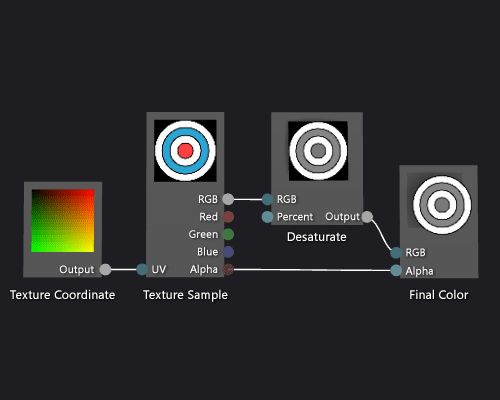
The following illustration shows the completed shader graph and a preview of the shader applied to a cube.
In this illustration, a plane is used as the preview shape, and a texture has been specified to better demonstrate the effect of the shader. Certain shapes might provide better previews for some shaders. To learn more about previewing shaders, see Shader Designer.
Create geometry-based gradient shaders
Use the Shader Designer and the Directed Graph Shader Language to create a geometry-based gradient shader. This shader scales a constant RGB color value by the height of each point of an object in world space.
You can implement a geometry-based shader by incorporating the position of the pixel into your shader. In shading languages, a pixel contains more information than just its color and location on a 2D screen. A pixel—known as a fragment in some systems—is a collection of values that describe the surface that corresponds to a pixel. The shader that's described in this document utilizes the height of each pixel of a 3D object in world space to affect the final output color of the fragment.
Before you begin, make sure that the Properties window and the Toolbox are displayed.
Create a DGSL shader with which to work. For information about how to add a DGSL shader to your project, see the Getting Started section in About the Shader Designer.
Disconnect the Point Color node from the Final Color node. Choose the RGB terminal of the Point Color node, and then choose Break Links. This makes room for the node that's added in the next step.
Add a Multiply node to the graph. In the Toolbox, under Math, select Multiply and move it to the design surface.
Add a Mask Vector node to the graph. In the Toolbox, under Utility, select Mask Vector and move it to the design surface.
Specify mask values for the Mask Vector node. In Select mode, select the Mask Vector node, and then in the Properties window, set the Green / Y property to True, and then set the Red / X, Blue / Z and Alpha / W properties to False. In this example, the Red / X, Green / Y, and Blue / Z properties correspond to the x, y, and z components of the World Position node, and Alpha / W is unused. Because only Green / Y is set to True, only the y component of the input vector remains after it is masked.
Add a World Position node to the graph. In the Toolbox, under Constants, select World Position and move it to the design surface.
Mask the world space position of the fragment. In Select mode, move the Output terminal of the World Position node to the Vector terminal of the Mask Vector node. This connection masks the position of the fragment to ignore the x and z components.
Multiply the RGB color constant by the masked world space position. Move the RGB terminal of the Point Color node to the Y terminal of the Multiply node, and then move the Output terminal of the Mask Vector node to the X terminal of the Multiply node. This connection scales the color value by the height of the pixel in world space.
Connect the scaled color value to the final color. Move the Output terminal of the Multiply node to the RGB terminal of the Final Color node.
The following illustration shows the completed shader graph and a preview of the shader applied to a sphere.
Note
In this illustration, an orange color is specified to better demonstrate the effect of the shader, but because the preview shape has no position in world-space, the shader cannot be fully previewed in the Shader Designer. The shader must be previewed in a real scene to demonstrate the full effect.

Certain shapes might provide better previews for some shaders. To learn more about previewing shaders, see Shader Designer.
The following illustration shows the shader that's described in this document applied to the 3D scene that's demonstrated in How to: Model 3D terrain. The intensity of the color increases with the height of the point in the world.
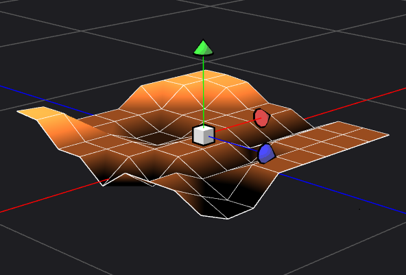
For more information about how to apply a shader to a 3D model, see How to: Apply a shader to a 3D model.
Related content
Feedback
Coming soon: Throughout 2024 we will be phasing out GitHub Issues as the feedback mechanism for content and replacing it with a new feedback system. For more information see: https://aka.ms/ContentUserFeedback.
Submit and view feedback for