GPIO WinRT Functional and Stress Tests
The GPIO tests do functional and stress testing of GPIO drivers through the WinRT APIs. The scope of testing includes:
- Verification that reading, writing, and interrupts work on all pins by using loopbacks. See description of Board.xml below to specify loopback configuration.
- Verification that a pin reverts to its default state when its handle is closed.
- Verification that the expected pins are exposed by comparing the enumerated pins against a configuration file (see description of Board.xml below).
- Verification that the state of a pin can be tracked reliably using interrupts.
- Verification that the drivers behave correctly under stress conditions. The stress tests toggle two sets of loopback pins in parallel and verify that the pin value as returned by Read() is correct and that interrupts are fired at the correct times.
Test details
| Specifications |
|
| Platforms | |
| Supported Releases |
|
| Expected run time (in minutes) | 5 |
| Category | Development |
| Timeout (in minutes) | 10000 |
| Requires reboot | false |
| Requires special configuration | true |
| Type | automatic |
Additional documentation
Tests in this feature area might have additional documentation, including prerequisites, setup, and troubleshooting information, that can be found in the following topic(s):
Running the test
The GPIO functional and stress tests require a minimum of 4 pins to run. These pin numbers are referred to as A1, A2, B1, and B2. A1 must be connected to A2 through a 1k resistor, and B1 must be connected to B2 through a 1k resistor as shown in the following schematic:
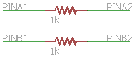
The resistors protect the hardware from damage during output contention and are necessary for the tests to validate drive modes. You will be prompted to supply the pin numbers of A1, A2, B1, and B2 when you schedule the tests for execution. If you're running the tests from the command line, you must specify the pin numbers with the 'Pins' runtime parameter as shown in the Troubleshooting section.
In the tests' default configuration, only the 4 pins specified above will be run. While this is sufficient to gain coverage of the controller driver, it is also necessary to validate that every exposed pin can be used for IO and interrupts. To run loopback tests on all pins, connect every two pins together through a 1k resistor, then modify %programfiles(x86)%\Windows Kits\10\Hardware Lab Kit\Tests\<arch>\iot\Board.xml as follows:
Under the <Table Id="Pins"> element, add a <Row> for each exposed pin, where DefaultDriveMode specifies the drive mode you're expecting the pin to be in when the board is powered on. DefaultDriveMode must be one of the values in the Windows.Devices.Gpio.GpioPinDriveMode enumeration.
          <Table Id="Pins">
            <Row>
              <Parameter Name="PinNumber">0</Parameter>
              <Parameter Name="Enabled">True</Parameter>
              <Parameter Name="DefaultDriveMode">Input</Parameter>
            </Row>
            <Row>
              <Parameter Name="PinNumber">1</Parameter>
              <Parameter Name="Enabled">True</Parameter>
              <Parameter Name="DefaultDriveMode">InputPullUp</Parameter>
            </Row>
            <!-- By setting Enabled to False, you can also assert that a pin should NOT be accessible -->
            <Row>
              <Parameter Name="PinNumber">2</Parameter>
              <Parameter Name="Enabled">False</Parameter>
            </Row>
          </Table>
Under the <Table Id="Loopbacks"> element, add a <Row> for each pair of pins that is connected in loopback configuration. For example, the following data specifies that pin 0 is connected to pin 2 and pin 1 is connected to pin 3.
          <Table Id="Loopbacks">
            <Row>
              <Parameter Name="Pin1">0</Parameter>
              <Parameter Name="Pin2">2</Parameter>
            </Row>
            <Row>
              <Parameter Name="Pin1">1</Parameter>
              <Parameter Name="Pin2">3</Parameter>
            </Row>
          </Table>
Board-rpi.xml and Board-mbm.xml are provided in %programfiles(x86)%\Windows Kits\10\Hardware Lab Kit\Tests\<arch>\iot as examples for the Raspberry Pi and MinnowBoardMax platforms.
Board.xml must be present in the same directory as Windows.Devices.LowLevel.UnitTests.dll when the tests are run. If you run the tests through HLK manager, it will automatically copy Board.xml from the HLK directory to the correct location on the device. If you run the tests on the command line, you must deploy Board.xml yourself.
Troubleshooting
For generic troubleshooting of HLK test failures, see Troubleshooting Windows HLK Test Failures.
We recommend running the tests on the command line to gain insight into failures and to quickly iterate on solutions. Here's how to run the tests on the command line:
Copy %programfiles(x86)%\Windows Kits\10\Testing\Runtimes\TAEF\<arch>\MinTe to c:\data\minte
Copy all files in %programfiles(x86)%\Windows Kits\10\Hardware Lab Kit\Tests\<arch>\iot to c:\data on your device.
Telnet or ssh into your device
Change directories to c:\data
Run
minte\te.exe windows.devices.lowlevel.unittests.dll /p:Pins=A1,A2,B1,B2 /name:GpioTests::*
Command line test usage:
minte\te.exe windows.devices.lowlevel.unittests.dll [/p:Pins=pin_numbers] [/name:test_name] [/p:Duration=duration]
- pin_numbers - the pin numbers to use for testing, of the form A1,A2,B1,B2 where A1 is connected to A2 through a 1k resistor and B1 is connected to B2 through a 1k resistor. If not specified, A1 defaults to the lowest available pin number, A2 defaults to the highest available pin number, B1 defaults to the second lowest available pin number, and B2 defaults to the second highest available pin number. Example: /p:Pins=4,27,5,26
- test_name - the name of the test to run which may include wildcards. Examples: /name:GpioTests::*, /name:GpioTests::VerifySetDriveMode#metadataSet0
- duration - how long to run stress tests. Examples: /p:Duration=10s (10 seconds), /p:Duration=1m (1 minute), /p:Duration=2h (2 hours), /p:Duration=1d (1 day)
To run the tests in default configuration,
minte\te.exe windows.devices.lowlevel.unittests.dll /p:Pins=0,1,2,3 /name:GpioTests::*
To run a specific test, pass the full test name to the /name parameter:
minte\te.exe windows.devices.lowlevel.unittests.dll /p:Pins=0,1,2,3 /name:GpioTests::VerifyInterruptStateTracking
To run the stress tests for the recommended duration of 2 hours each, run:
minte\te.exe windows.devices.lowlevel.unittests.dll /p:Pins=0,1,2,3 /name:GpioTests::* /p:Duration=2h
A tool that can help with manual troubleshooting is GpioTestTool, a simple utility for interacting with GPIO from the command line.
More information
Parameters
| Parameter name | Parameter description |
|---|---|
| Pins | Loopback pins of the form <A1>,<A2>,<B1>,<B2> where A1 is connected to A2, and B1 is connected to B2 |
| Duration | Specifies how long to run each of the stress tests. e.g. 30s, 1m, 1h, 1d |