Raspberry Pi 2 和 3 引脚映射
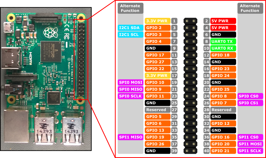
Raspberry Pi 2 和 Raspberry Pi 3 的硬件接口通过板上的 40 引脚标头 J8 公开。 功能包括:
- 24x - GPIO 引脚
- 1x - 串行 UART(RPi3 仅包含微型 UART)
- 2x - SPI 总线
- 1x - I2C 总线
- 2x - 5V 电源引脚
- 2x - 3.3V 电源引脚
- 8x - 地面引脚
GPIO 引脚
让我们看看此设备上提供的 GPIO。
GPIO 引脚概述
可通过 API 访问以下 GPIO 引脚:
GPIO# 开机拉取 交替功能 标头引脚 2 PullUp I2C1 SDA 3 3 PullUp I2C1 SCL 5 4 PullUp 7 5 PullUp 29 6 PullUp 31 7 PullUp SPI0 CS1 26 8 PullUp SPI0 CS0 24 9 下拉 SPI0 MISO 21 10 下拉 SPI0 MOSI 19 11 下拉 SPI0 SCLK 23 12 下拉 32 13 下拉 33 16 下拉 SPI1 CS0 36 17 下拉 11 18 下拉 12 19 下拉 SPI1 MISO 35 20 下拉 SPI1 MOSI 38 21 下拉 SPI1 SCLK 40 22 下拉 15 23 下拉 16 24 下拉 18 25 下拉 22 26 下拉 37 27 下拉 13 35* PullUp 红色电源 LED 47* PullUp 绿色活动 LED
* = 仅 Raspberry Pi 2。 Raspberry Pi 3 上不提供 GPIO 35 和 47。
GPIO 示例
例如,以下代码将打开 GPIO 5 作为输出,并将数字“1”写在引脚上:
using Windows.Devices.Gpio;

public void GPIO()
{
    // Get the default GPIO controller on the system
    GpioController gpio = GpioController.GetDefault();
    if (gpio == null)
        return; // GPIO not available on this system

    // Open GPIO 5
    using (GpioPin pin = gpio.OpenPin(5))
    {
        // Latch HIGH value first. This ensures a default value when the pin is set as output
        pin.Write(GpioPinValue.High);

        // Set the IO direction as output
        pin.SetDriveMode(GpioPinDriveMode.Output);

    } // Close pin - will revert to its power-on state
}
打开引脚时,它将处于其通电状态,可能包括上拉电阻。 若要断开拉取阀的连接并获取高电压输入,请将驱动器模式设置为 GpioPinDriveMode.Input:
pin.SetDriveMode(GpioPinDriveMode.Input);
当引脚关闭时,它还原其开机状态。
引脚复用
某些 GPIO 引脚可以执行多个功能。 默认情况下,引脚配置为 GPIO 输入。 通过调用 I2cDevice.FromIdAsync() 或 SpiDevice.FromIdAsync() 打开交替功能,该功能所需的引脚会自动切换(“复用”)为正确的功能。 通过调用 I2cDevice.Dispose() 或 SpiDevice.Dispose() 关闭设备时,引脚会还原为其默认功能。 如果尝试同时对两个不同的功能使用一个引脚,则在尝试打开冲突功能时会引发异常。 例如,
var controller = GpioController.GetDefault();
var gpio2 = controller.OpenPin(2);      // open GPIO2, shared with I2C1 SDA

var dis = await DeviceInformation.FindAllAsync(I2cDevice.GetDeviceSelector());
var i2cDevice = await I2cDevice.FromIdAsync(dis[0].Id, new I2cConnectionSettings(0x55)); // exception thrown because GPIO2 is open

gpio2.Dispose(); // close GPIO2
var i2cDevice = await I2cDevice.FromIdAsync(dis[0].Id, new I2cConnectionSettings(0x55)); // succeeds because gpio2 is now available

var gpio2 = controller.OpenPin(2); // throws exception because GPIO2 is in use as SDA1

i2cDevice.Dispose(); // release I2C device
var gpio2 = controller.OpenPin(2); // succeeds now that GPIO2 is available
串行 UART
RPi2/3 上提供了一个串行 UART: UART0
- 引脚 8 - UART0 TX
- 引脚 10 - UART0 RX
以下示例初始化 UART0 并执行后跟读取的写入:
using Windows.Storage.Streams;
using Windows.Devices.Enumeration;
using Windows.Devices.SerialCommunication;

public async void Serial()
{
    string aqs = SerialDevice.GetDeviceSelector("UART0");                   /* Find the selector string for the serial device   */
    var dis = await DeviceInformation.FindAllAsync(aqs);                    /* Find the serial device with our selector string  */
    SerialDevice SerialPort = await SerialDevice.FromIdAsync(dis[0].Id);    /* Create an serial device with our selected device */

    /* Configure serial settings */
    SerialPort.WriteTimeout = TimeSpan.FromMilliseconds(1000);
    SerialPort.ReadTimeout = TimeSpan.FromMilliseconds(1000);
    SerialPort.BaudRate = 9600;                                             /* mini UART: only standard baud rates */
    SerialPort.Parity = SerialParity.None;                                  /* mini UART: no parities */
    SerialPort.StopBits = SerialStopBitCount.One;                           /* mini UART: 1 stop bit */
    SerialPort.DataBits = 8;

    /* Write a string out over serial */
    string txBuffer = "Hello Serial";
    DataWriter dataWriter = new DataWriter();
    dataWriter.WriteString(txBuffer);
    uint bytesWritten = await SerialPort.OutputStream.WriteAsync(dataWriter.DetachBuffer());

    /* Read data in from the serial port */
    const uint maxReadLength = 1024;
    DataReader dataReader = new DataReader(SerialPort.InputStream);
    uint bytesToRead = await dataReader.LoadAsync(maxReadLength);
    string rxBuffer = dataReader.ReadString(bytesToRead);
}
请注意,必须将以下功能添加到 UWP 项目中的 Package.appxmanifest 文件以运行串行 UART 代码:
Visual Studio 2017 的清单设计器(用于 appxmanifest 文件的可视化编辑器)中存在影响 serialcommunication 功能的已知 bug。 如果 appxmanifest 添加了 serialcommunication 功能,则使用设计器修改 appxmanifest 将损坏 appxmanifest(设备 xml 子级将丢失)。 可以通过右键单击 appxmanifest 并从上下文菜单中选择“查看代码”来手动编辑 appxmanifest 以解决此问题。
  <Capabilities>
    <DeviceCapability Name="serialcommunication">
      <Device Id="any">
        <Function Type="name:serialPort" />
      </Device>
    </DeviceCapability>
  </Capabilities>
I2C 总线
让我们看看此设备上提供的 I2C 总线。
I2C 概述
在引脚标头上公开了一个 I2C 控制器 I2C1 ,其中包含两行 SDA 和 SCL。 用于此总线的 1.8KΩ 内部上拉电阻已安装在开发板上。
信号名称 标头引脚号 Gpio 编号 SDA 3 2 SCL 5 3
以下示例初始化 I2C1 并将数据写入地址 0x40的 I2C 设备:
using Windows.Devices.Enumeration;
using Windows.Devices.I2c;

public async void I2C()
{
    // 0x40 is the I2C device address
    var settings = new I2cConnectionSettings(0x40);
    // FastMode = 400KHz
    settings.BusSpeed = I2cBusSpeed.FastMode;

    // Create an I2cDevice with the specified I2C settings
    var controller = await I2cController.GetDefaultAsync();

    using (I2cDevice device = controller.GetDevice(settings))
    {
        byte[] writeBuf = { 0x01, 0x02, 0x03, 0x04 };
        device.Write(writeBuf);
    }
}
SPI 总线
RPi2/3 提供了两个 SPI 总线控制器。
SPI0
信号名称 标头引脚号 Gpio 编号 MOSI 19 10 MISO 21 9 SCLK 23 11 CS0 24 8 CS1 26 7
SPI1
信号名称 标头引脚号 Gpio 编号 MOSI 38 20 MISO 35 19 SCLK 40 21 CS0 36 16
SPI 示例
有关如何使用芯片选择 0 在总线 SPI0 上执行 SPI 写入的示例如下所示:
using Windows.Devices.Enumeration;
using Windows.Devices.Spi;

public async void SPI()
{
    // Use chip select line CS0
    var settings = new SpiConnectionSettings(0);
    // Set clock to 10MHz
    settings.ClockFrequency = 10000000;

    // Get a selector string that will return our wanted SPI controller
    string aqs = SpiDevice.GetDeviceSelector("SPI0");

    // Find the SPI bus controller devices with our selector string
    var dis = await DeviceInformation.FindAllAsync(aqs);

    // Create an SpiDevice with our selected bus controller and Spi settings
    using (SpiDevice device = await SpiDevice.FromIdAsync(dis[0].Id, settings))
    {
        byte[] writeBuf = { 0x01, 0x02, 0x03, 0x04 };
        device.Write(writeBuf);
    }
}