绘制图形对象
 浏览示例
浏览示例Microsoft.Maui.Graphics 命名空间中的.NET Multi-platform App UI (.NET MAUI) 图形支持在定义为 ICanvas 对象的画布上绘制图形对象。
.NET MAUI GraphicsView 控件提供对 ICanvas 对象的访问,可以在该对象上设置属性并调用方法来绘制图形对象。 要详细了解 GraphicsView,请参阅 GraphicsView。
注意
许多图形对象具有 Draw 和 Fill 方法,例如 DrawRectangle 和 FillRectangle。 Draw 方法绘制形状的轮廓,但不填充该轮廓。 Fill 方法绘制形状的轮廓,且填充该轮廓。
可在 ICanvas 上使用每个平台均识别的与设备无关的单位绘制图形对象。 这可确保图形对象根据基础平台的像素密度相应缩放。
绘制线条
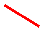
可以使用 DrawLine 方法在 ICanvas 上绘制线条,这需要四个表示线条起点和终点的 float 参数。
以下示例演示如何绘制线条:
canvas.StrokeColor = Colors.Red;
canvas.StrokeSize = 6;
canvas.DrawLine(10, 10, 90, 100);
在此示例中,从 (10,10) 到 (90,100) 绘制红色对角线:
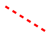
以下示例演示如何绘制虚线:
canvas.StrokeColor = Colors.Red;
canvas.StrokeSize = 4;
canvas.StrokeDashPattern = new float[] { 2, 2 };
canvas.DrawLine(10, 10, 90, 100);
在此示例中,从 (10,10) 到 (90,100) 绘制红色虚线对角线:
有关虚线的详细信息,请参阅绘制虚线对象。
绘制椭圆形
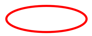
可以使用 DrawEllipse 方法在 ICanvas 上绘制椭圆和圆,这需要类型为 float 的 x、y、width 和 height 参数。
以下示例演示如何绘制椭圆:
canvas.StrokeColor = Colors.Red;
canvas.StrokeSize = 4;
canvas.DrawEllipse(10, 10, 100, 50);
在此示例中,在 (10,10) 处绘制了尺寸为 100x50 的红色椭圆:
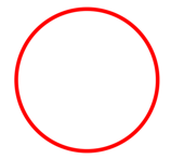
要绘制圆,请使 DrawEllipse 方法的 width 和 height 参数相等:
canvas.StrokeColor = Colors.Red;
canvas.StrokeSize = 4;
canvas.DrawEllipse(10, 10, 100, 100);
在此示例中,在 (10,10) 处绘制了尺寸为 100x100 的红色圆:
注意
也可以使用 DrawCircle 方法绘制圆。
有关绘制虚线椭圆的信息,请参阅绘制虚线对象。
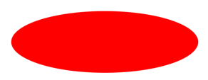
可以使用 FillEllipse 方法绘制实心椭圆,该方法还需要类型为 float 的 x、y、width 和 height 参数:
canvas.FillColor = Colors.Red;
canvas.FillEllipse(10, 10, 150, 50);
在此示例中,在 (10,10) 处绘制了尺寸为 150x50 的红色实心椭圆:
调用 FillEllipse 方法之前,必须将 ICanvas 对象的 FillColor 属性设置为 Color。
也可以使用 FillCircle 方法绘制实心圆。
注意
存在采用 Rect 和 RectF 参数的 DrawEllipse 和 FillEllipse 重载。 此外,还有 DrawCircle 和 FillCircle 重载。
绘制矩形
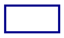
可以使用 DrawRectangle 方法在 ICanvas 上绘制矩形和正方形,该方法需要类型为 float 的 x、y、width 和 height 参数。
以下示例演示如何绘制矩形:
canvas.StrokeColor = Colors.DarkBlue;
canvas.StrokeSize = 4;
canvas.DrawRectangle(10, 10, 100, 50);
在此示例中,在 (10,10) 处绘制了尺寸为 100x50 的深蓝色矩形:
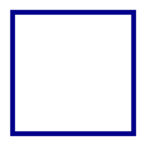
要绘制正方形,请使 DrawRectangle 方法的 width 和 height 参数相等:
canvas.StrokeColor = Colors.DarkBlue;
canvas.StrokeSize = 4;
canvas.DrawRectangle(10, 10, 100, 100);
在此示例中,在 (10,10) 处绘制了尺寸为 100x100 的深蓝色正方形:
要详细了解绘制虚线矩形,请参阅绘制虚线对象。
可以使用 FillRectangle 方法绘制实心矩形,该方法还需要类型为 float 的 x、y、width 和 height 参数:
canvas.FillColor = Colors.DarkBlue;
canvas.FillRectangle(10, 10, 100, 50);
在此示例中,在 (10,10) 处绘制了尺寸为 100x50 的深蓝色实心矩形:

调用 FillRectangle 方法之前,必须将 ICanvas 对象的 FillColor 属性设置为 Color。
注意
存在采用 Rect 和 RectF 参数的 DrawRectangle 和 FillRectangle 重载。
绘制圆角矩形
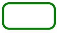
可以使用 DrawRoundedRectangle 方法在 ICanvas 上绘制圆角矩形和正方形,该方法需要类型为 float 的 x、y、width、height 和 cornerRadius 参数。 cornerRadius 参数指定用于对矩形做圆角处理的半径。
以下示例演示如何绘制圆角矩形:
canvas.StrokeColor = Colors.Green;
canvas.StrokeSize = 4;
canvas.DrawRoundedRectangle(10, 10, 100, 50, 12);
在此示例中,在 (10,10) 处绘制了尺寸为 100x50 的绿色圆角矩形:
有关绘制虚线圆角矩形的信息,请参阅绘制虚线对象。
可以使用 FillRoundedRectangle 方法绘制实心圆角矩形,该方法还需要类型为 float 的 x、y、width、height 和 cornerRadius 参数:
canvas.FillColor = Colors.Green;
canvas.FillRoundedRectangle(10, 10, 100, 50, 12);
在此示例中,在 (10,10) 处绘制了尺寸为 100x50 的绿色实心圆角矩形:

调用 FillRoundedRectangle 方法之前,必须将 ICanvas 对象的 FillColor 属性设置为 Color。
注意
存在采用 Rect 和 RectF 参数的 DrawRoundedRectangle 和 FillRoundedRectangle 重载,以及支持单独指定每个角半径的重载。
绘制弧形
可以使用 DrawArc 方法在 ICanvas 上绘制圆弧,该方法需要类型为 float 的 x、y、width、height、startAngle 和 endAngle 参数,以及类型为 bool 的 clockwise 和 closed 参数。 startAngle 参数指定从 x 轴到圆弧起点的角度。endAngle 参数指定从 x 轴到圆弧终点的角度。clockwise 参数指定绘制圆弧的方向,closed 参数指定圆弧的终点是否连接到起点。
以下示例演示如何绘制圆弧:
canvas.StrokeColor = Colors.Teal;
canvas.StrokeSize = 4;
canvas.DrawArc(10, 10, 100, 100, 0, 180, true, false);
在此示例中,在 (10,10) 处绘制了尺寸为 100x100 的蓝绿色圆弧。 圆弧以顺时针方向从 0 度到 180 度绘制,并且不闭合:

有关绘制虚线圆弧的信息,请参阅绘制虚线对象。
可以使用 FillArc 方法绘制实心圆弧,该方法需要类型为 float 的 x、y、width、height、startAngle 和 endAngle 参数,以及类型为 bool 的 clockwise 参数:
canvas.FillColor = Colors.Teal;
canvas.FillArc(10, 10, 100, 100, 0, 180, true);
在此示例中,在 (10,10) 处绘制了尺寸为 100x100 的蓝绿色实心圆弧。 该圆弧沿顺时针方向从 0 度到 180 度绘制,并自动闭合:

调用 FillArc 方法之前,必须将 ICanvas 对象的 FillColor 属性设置为 Color。
绘制路径
路径是一个或多个轮廓的集合。 每个轮廓都是连接的直线和曲线的集合。 轮廓间相互不连接,但它们在视觉上可能会重叠。 有时,单个轮廓可以重叠其本身。
路径用于绘制曲线和复杂形状,可以使用 DrawPath 方法在 ICanvas 上绘制,该方法需要 PathF 参数。
轮廓通常以调用 PathF.MoveTo 方法开始,可以将其表示为 PointF 值,也可以表示为单独的 x 和 y 坐标。 MoveTo 调用在轮廓的起点处建立一个点和一个初始当前点。 然后,可以调用以下方法,以便使用直线或曲线将轮廓从当前点继续绘制到方法中指定的点(随后成为新的当前点):
这些方法均不包含描述直线或曲线所需的所有数据。 相反,每个方法都使用紧邻其前面的方法调用建立的当前点。 例如,LineTo 方法基于当前点向轮廓添加直线。
轮廓在再次调用 MoveTo 时结束,新轮廓由此开始,或者在调用 Close 时结束,这将使轮廓闭合。 Close 方法自动将直线从当前点追加到轮廓的第一个点,并将路径标记为闭合。
PathF 类还定义其他方法和属性。 以下方法将整个轮廓添加到路径:
- AppendEllipse 将闭合椭圆轮廓追加到路径。
- AppendCircle 将闭合圆轮廓追加到路径。
- AppendRectangle 将闭合矩形轮廓追加到路径。
- AppendRoundedRectangle 将闭合圆角矩形追加到路径。
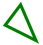
以下示例展示如何绘制路径:
PathF path = new PathF();
path.MoveTo(40, 10);
path.LineTo(70, 80);
path.LineTo(10, 50);
path.Close();
canvas.StrokeColor = Colors.Green;
canvas.StrokeSize = 6;
canvas.DrawPath(path);
在此示例中,绘制了绿色闭合三角形:
可以使用 FillPath 绘制实心路径,这也需要 PathF 参数:
PathF path = new PathF();
path.MoveTo(40, 10);
path.LineTo(70, 80);
path.LineTo(10, 50);
canvas.FillColor = Colors.SlateBlue;
canvas.FillPath(path);
在此示例中,绘制了石板蓝实心三角形:

调用 FillPath 方法之前,必须将 ICanvas 对象的 FillColor 属性设置为 Color。
重要
FillPath 方法包含支持指定 WindingMode 的重载,从而设置使用的填充算法。 有关详细信息,请参阅绕组模式。
绘制图像
可以使用 DrawImage 方法在 ICanvas 上绘制图像,该方法需要 IImage 参数,以及类型为 float 的 x、y、width 和 height 参数。
以下示例展示如何加载图像并将其绘制到画布:
using System.Reflection;
using IImage = Microsoft.Maui.Graphics.IImage;
#if IOS || ANDROID || MACCATALYST
using Microsoft.Maui.Graphics.Platform;
#elif WINDOWS
using Microsoft.Maui.Graphics.Win2D;
#endif

IImage image;
Assembly assembly = GetType().GetTypeInfo().Assembly;
using (Stream stream = assembly.GetManifestResourceStream("GraphicsViewDemos.Resources.Images.dotnet_bot.png"))
{
#if IOS || ANDROID || MACCATALYST
    // PlatformImage isn't currently supported on Windows.
    image = PlatformImage.FromStream(stream);
#elif WINDOWS
    image = new W2DImageLoadingService().FromStream(stream);
#endif
}

if (image != null)
{
    canvas.DrawImage(image, 10, 10, image.Width, image.Height);
}
using System.Reflection;
using IImage = Microsoft.Maui.Graphics.IImage;
using Microsoft.Maui.Graphics.Platform;

IImage image;
Assembly assembly = GetType().GetTypeInfo().Assembly;
using (Stream stream = assembly.GetManifestResourceStream("GraphicsViewDemos.Resources.Images.dotnet_bot.png"))
{
    image = PlatformImage.FromStream(stream);
}

if (image != null)
{
    canvas.DrawImage(image, 10, 10, image.Width, image.Height);
}
在此示例中,从程序集中检索图像并作为流加载。 然后,在 (10,10) 处以实际大小绘制它:

重要
加载嵌入程序集中的图像需要该图像将其生成操作设置为嵌入式资源,而不是 MauiImage。
绘制字符串
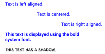
可以使用其中一个 DrawString 重载在 ICanvas 上绘制字符串。 可以通过设置 Font、FontColor 和 FontSize 属性定义每个字符串的外观。 可以通过水平和垂直对齐选项指定字符串对齐方式,这些选项在字符串的边界框内执行对齐操作。
注意
字符串的边界框由其 x、y、width 和 height 参数定义。
以下示例展示如何绘制字符串:
canvas.FontColor = Colors.Blue;
canvas.FontSize = 18;

canvas.Font = Font.Default;
canvas.DrawString("Text is left aligned.", 20, 20, 380, 100, HorizontalAlignment.Left, VerticalAlignment.Top);
canvas.DrawString("Text is centered.", 20, 60, 380, 100, HorizontalAlignment.Center, VerticalAlignment.Top);
canvas.DrawString("Text is right aligned.", 20, 100, 380, 100, HorizontalAlignment.Right, VerticalAlignment.Top);

canvas.Font = Font.DefaultBold;
canvas.DrawString("This text is displayed using the bold system font.", 20, 140, 350, 100, HorizontalAlignment.Left, VerticalAlignment.Top);

canvas.Font = new Font("Arial");
canvas.FontColor = Colors.Black;
canvas.SetShadow(new SizeF(6, 6), 4, Colors.Gray);
canvas.DrawString("This text has a shadow.", 20, 200, 300, 100, HorizontalAlignment.Left, VerticalAlignment.Top);
在此示例中,显示了具有不同外观和对齐选项的字符串:
注意
DrawString 重载还支持指定截断和行距。
有关绘制阴影的信息,请参阅绘制阴影。
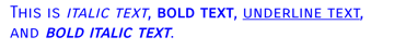
绘制特性化文本
可以使用 DrawText 方法在 ICanvas 上绘制特性化文本,该方法需要 IAttributedText 参数,以及类型为 float 的 x、y、width 和 height 参数。 特性化文本是一个字符串,其中包含其文本部分的关联特性,通常表示样式数据。
以下示例展示如何绘制特性化文本:
using Microsoft.Maui.Graphics.Text;
...

canvas.Font = new Font("Arial");
canvas.FontSize = 18;
canvas.FontColor = Colors.Blue;

string markdownText = @"This is *italic text*, **bold text**, __underline text__, and ***bold italic text***.";
IAttributedText attributedText = MarkdownAttributedTextReader.Read(markdownText); // Requires the Microsoft.Maui.Graphics.Text.Markdig package
canvas.DrawText(attributedText, 10, 10, 400, 400);
在此示例中,将 Markdown 转换为特性化文本,并以正确的样式显示:
重要
绘制特性化文本需要你已将 Microsoft.Maui.Graphics.Text.Markdig NuGet 包添加到项目。
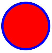
使用填充和描边进行绘制
可以在填充方法之后通过调用绘图方法,将同时包含填充和描边的图形对象绘制到画布。 例如,要绘制空心矩形,请将 FillColor 和 StrokeColor 属性设置为颜色,然后依次调用 FillRectangle 方法和 DrawRectangle 方法。
以下示例绘制有描边轮廓的实心圆作为路径:
float radius = Math.Min(dirtyRect.Width, dirtyRect.Height) / 4;

PathF path = new PathF();
path.AppendCircle(dirtyRect.Center.X, dirtyRect.Center.Y, radius);

canvas.StrokeColor = Colors.Blue;
canvas.StrokeSize = 10;
canvas.FillColor = Colors.Red;

canvas.FillPath(path);
canvas.DrawPath(path);
在此示例中,指定了 PathF 对象的描边和填充颜色。 绘制实心圆,接着绘制圆的轮廓描边:
警告
在填充方法之前调用绘图方法将导致 z 顺序不正确。 将在描边之上绘制填充,并且描边将不可见。
绘制阴影
在 ICanvas 上绘制的图形对象可以使用 SetShadow 方法应用阴影,该方法采用以下参数:
以下示例展示如何向填充的对象添加阴影:
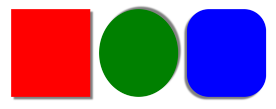
canvas.FillColor = Colors.Red;
canvas.SetShadow(new SizeF(10, 10), 4, Colors.Grey);
canvas.FillRectangle(10, 10, 90, 100);

canvas.FillColor = Colors.Green;
canvas.SetShadow(new SizeF(10, -10), 4, Colors.Grey);
canvas.FillEllipse(110, 10, 90, 100);

canvas.FillColor = Colors.Blue;
canvas.SetShadow(new SizeF(-10, 10), 4, Colors.Grey);
canvas.FillRoundedRectangle(210, 10, 90, 100, 25);
在这些示例中,使用相同的模糊量将光源位于不同位置的阴影添加到填充的对象中:
绘制虚线对象
ICanvas 对象包含类型为 float[] 的 StrokeDashPattern 属性。 此属性是 float 值的数组,这些值指示在绘制对象的描边时要使用的虚线和间隙的图案。 数组中的每个 float 都指定虚线或间隙的长度。 数组中的第一项指定虚线的长度,而数组中的第二项指定间隙的长度。 因此,索引值为偶数的 float 值指定虚线,而索引值为奇数的 float 值指定间隙。
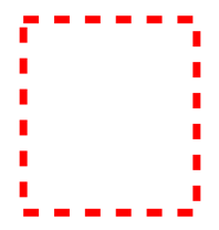
以下示例展示如何使用规则虚线绘制虚线正方形:
canvas.StrokeColor = Colors.Red;
canvas.StrokeSize = 4;
canvas.StrokeDashPattern = new float[] { 2, 2 };
canvas.DrawRectangle(10, 10, 90, 100);
在此示例中,绘制了带有规则虚线描边的正方形:
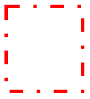
以下示例展示如何使用不规则虚线绘制虚线正方形:
canvas.StrokeColor = Colors.Red;
canvas.StrokeSize = 4;
canvas.StrokeDashPattern = new float[] { 4, 4, 1, 4 };
canvas.DrawRectangle(10, 10, 90, 100);
在此示例中,绘制了带有不规则虚线描边的正方形:
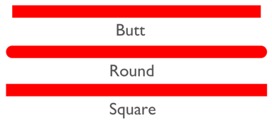
控制直线终点
一条线由三部分组成:起点线帽、线本体和终点线帽。 起点和终点线帽描述线条的起点和终点。
ICanvas 对象包含类型为 LineCap 的 StrokeLineCap 属性,用于描述线条的起点和终点。 LineCap 枚举定义以下成员:
Butt,表示终点为正方形的线条,一直绘制到线条的确切终结点。 这是 StrokeLineCap 属性的默认值。Round,表示终点为圆形的线条。Square,表示终点为正方形的线条,一直绘制到终结点以外相当于线条宽度一半的距离。
下面的示例演示如何设置 StrokeLineCap 属性:
canvas.StrokeSize = 10;
canvas.StrokeColor = Colors.Red;
canvas.StrokeLineCap = LineCap.Round;
canvas.DrawLine(10, 10, 110, 110);
在此示例中,红色直线在其起点和终点处做圆角处理:
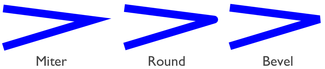
控制直线联接
ICanvas 对象包含类型为 LineJoin 的 StrokeLineJoin 属性,该属性指定在对象顶点处使用的联接类型。 LineJoin 枚举定义以下成员:
Miter,表示形成尖角或剪裁角的角顶点。 这是 StrokeLineJoin 属性的默认值。Round,表示在拐角处形成圆弧的圆形顶点。Bevel,表示形成对角的斜角顶点。
注意
当 StrokeLineJoin 属性设置为 Miter 时,可以将 MiterLimit 属性设置为 float,以限制对象中线条联接的斜接长度。
下面的示例演示如何设置 StrokeLineJoin 属性:
PathF path = new PathF();
path.MoveTo(10, 10);
path.LineTo(110, 50);
path.LineTo(10, 110);

canvas.StrokeSize = 20;
canvas.StrokeColor = Colors.Blue;
canvas.StrokeLineJoin = LineJoin.Round;
canvas.DrawPath(path);
在此示例中,蓝色 PathF 对象在其顶点处采用圆形联接:
剪裁对象
绘制到 ICanvas 的图形对象可以在绘制之前使用以下方法进行裁剪:
- ClipPath 剪裁对象,以便仅显示 PathF 对象区域中的区域。
- ClipRectangle 剪裁对象,以便仅显示矩形区域内的区域。 可以使用
float参数或通过 Rect 或 RectF 参数指定矩形。 - SubtractFromClip 剪裁对象,以便仅显示矩形区域之外的区域。 可以使用
float参数或通过 Rect 或 RectF 参数指定矩形。
以下示例展示如何使用 ClipPath 方法剪裁图像:
using System.Reflection;
using IImage = Microsoft.Maui.Graphics.IImage;
#if IOS || ANDROID || MACCATALYST
using Microsoft.Maui.Graphics.Platform;
#elif WINDOWS
using Microsoft.Maui.Graphics.Win2D;
#endif

IImage image;
Assembly assembly = GetType().GetTypeInfo().Assembly;
using (Stream stream = assembly.GetManifestResourceStream("GraphicsViewDemos.Resources.Images.dotnet_bot.png"))
{
#if IOS || ANDROID || MACCATALYST
    // PlatformImage isn't currently supported on Windows.
    image = PlatformImage.FromStream(stream);
#elif WINDOWS
    image = new W2DImageLoadingService().FromStream(stream);
#endif
}

if (image != null)
{
    PathF path = new PathF();
    path.AppendCircle(100, 90, 80);
    canvas.ClipPath(path);  // Must be called before DrawImage
    canvas.DrawImage(image, 10, 10, image.Width, image.Height);
}
using System.Reflection;
using IImage = Microsoft.Maui.Graphics.IImage;
using Microsoft.Maui.Graphics.Platform;

IImage image;
Assembly assembly = GetType().GetTypeInfo().Assembly;
using (Stream stream = assembly.GetManifestResourceStream("GraphicsViewDemos.Resources.Images.dotnet_bot.png"))
{
    image = PlatformImage.FromStream(stream);
}

if (image != null)
{
    PathF path = new PathF();
    path.AppendCircle(100, 90, 80);
    canvas.ClipPath(path);  // Must be called before DrawImage
    canvas.DrawImage(image, 10, 10, image.Width, image.Height);
}
在此示例中,使用 PathF 对象剪裁图像,该对象定义一个以 (100,90) 为圆心、80 为半径的圆。 结果是,只有位于圆内的图像部分才可见:

重要
ClipPath 方法包含支持指定 WindingMode 的重载,从而设置剪裁时使用的填充算法。 有关详细信息,请参阅绕组模式。
以下示例展示如何使用 SubtractFromClip 方法剪裁图像:
using System.Reflection;
using IImage = Microsoft.Maui.Graphics.IImage;
#if IOS || ANDROID || MACCATALYST
using Microsoft.Maui.Graphics.Platform;
#elif WINDOWS
using Microsoft.Maui.Graphics.Win2D;
#endif

IImage image;
Assembly assembly = GetType().GetTypeInfo().Assembly;
using (Stream stream = assembly.GetManifestResourceStream("GraphicsViewDemos.Resources.Images.dotnet_bot.png"))
{
#if IOS || ANDROID || MACCATALYST
    // PlatformImage isn't currently supported on Windows.
    image = PlatformImage.FromStream(stream);
#elif WINDOWS
    image = new W2DImageLoadingService().FromStream(stream);
#endif
}

if (image != null)
{
    canvas.SubtractFromClip(60, 60, 90, 90);
    canvas.DrawImage(image, 10, 10, image.Width, image.Height);
}
using System.Reflection;
using IImage = Microsoft.Maui.Graphics.IImage;
using Microsoft.Maui.Graphics.Platform;

IImage image;
Assembly assembly = GetType().GetTypeInfo().Assembly;
using (Stream stream = assembly.GetManifestResourceStream("GraphicsViewDemos.Resources.Images.dotnet_bot.png"))
{
    image = PlatformImage.FromStream(stream);
}

if (image != null)
{
    canvas.SubtractFromClip(60, 60, 90, 90);
    canvas.DrawImage(image, 10, 10, image.Width, image.Height);
}
在此示例中,从图像中剪裁提供给 SubtractFromClip 方法,并且由参数指定的矩形定义的区域。 结果是,只有位于矩形之外的图像部分才可见:

反馈
即将发布:在整个 2024 年,我们将逐步淘汰作为内容反馈机制的“GitHub 问题”,并将其取代为新的反馈系统。 有关详细信息,请参阅:https://aka.ms/ContentUserFeedback。
提交和查看相关反馈