HoloLens (第 1 代) 和 Azure 310:物件偵測
注意
混合實境學院教學課程的設計是以 HoloLens (第 1 代) 和混合實境沉浸式頭戴裝置為準。 因此,對於仍在尋找這些裝置開發指引的開發人員而言,我們覺得這些教學課程很重要。 這些教學課程不會使用用於 HoloLens 2 的最新工具組或互動進行更新。 系統會保留這些資訊,以繼續在支援的裝置上運作。 未來將會張貼一系列新的教學課程,示範如何針對 HoloLens 2 進行開發。 此通知會在張貼時更新這些教學課程的連結。
在此課程中,您將瞭解如何使用混合實境應用程式中的 Azure 自訂視覺「物件偵測」功能,辨識自定義視覺內容及其空間位置。
此服務可讓您使用物件影像來定型機器學習模型。 然後,您將使用定型的模型來辨識類似的物件,並在真實世界中近似其位置,如相機擷取 Microsoft HoloLens 或相機連線到計算機,以進行沉浸式 (VR) 頭戴式裝置。
Azure 自訂視覺 物件偵測是 Microsoft 服務,可讓開發人員建置自定義映射分類器。 然後,這些分類器可以搭配新的影像使用,藉由在影像本身內提供 Box 界限 來偵測該新影像內的物件。 此服務提供簡單、容易使用的在線入口網站,以簡化此程式。 如需詳細資訊,請流覽下列連結:
完成本課程之後,您將擁有混合實境應用程式,其可以執行下列動作:
- 用戶將能夠注視他們已使用 Azure 自訂視覺 服務、物件偵測定型的物件。
- 使用者將會使用 點 選手勢來擷取他們所查看專案的影像。
- 應用程式會將映像傳送至 Azure 自訂視覺 服務。
- 服務會有回復,將辨識結果顯示為世界空間文字。 這可透過利用 Microsoft HoloLens 的空間追蹤來完成,做為瞭解已辨識物件世界位置的方法,然後使用與影像中偵測到的標記相關聯的標籤提供標籤文字。
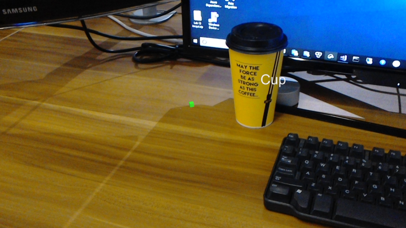
本課程也會涵蓋手動上傳影像、建立標籤,以及訓練服務以辨識所提供範例中 (的不同物件,方法是在您所提交的影像中設定 界限方 塊,以) 杯。
重要
在建立和使用應用程式之後,開發人員應該流覽回 Azure 自訂視覺 服務,並識別服務所做的預測,並判斷 (它們是否正確,並透過標記服務遺漏的任何專案,以及調整周框方塊) 。 接著,服務可以重新定型,這會增加辨識真實世界物件的可能性。
本課程將教導您如何將 Azure 自訂視覺 服務、物件偵測的結果取得至 Unity 型範例應用程式。 您必須將這些概念套用至您可能要建置的自定義應用程式。
裝置支援
| 課程 | HoloLens | 沉浸式頭戴裝置 |
|---|---|---|
| MR 和 Azure 310:物件偵測 | ✔️ |
必要條件
注意
本教學課程專為具備 Unity 和 C# 基本體驗的開發人員所設計。 另請注意,本檔中的必要條件和書面指示代表在撰寫 (2018 年 7 月) 時已經過測試和驗證的內容。 您可以自由使用最新的軟體,如 安裝工具 一文中所列,但不應假設本課程中的資訊完全符合您在較新軟體中找到的內容,而不是下面所列的內容。
針對本課程,我們建議使用下列硬體和軟體:
- 開發計算機
- 已啟用開發人員模式的 Windows 10 Fall Creators Update (或更新版本)
- 最新的 Windows 10 SDK
- Unity 2017.4 LTS
- Visual Studio 2017
- 已啟用開發人員模式的 Microsoft HoloLens
- Azure 安裝和 自訂視覺 服務擷取的因特網存取
- 每個您想要辨識 自訂視覺 的物件都需要至少 15 個 (15 個) 影像) 。 如果您想要,您可以使用本課程中已提供的影像, ) 一系列杯 子。
開始之前
- 若要避免建置此專案時發生問題,強烈建議您在根資料夾或近根資料夾中建立本教學課程中提及的專案, (長資料夾路徑可能會導致建置時間) 的問題。
- 設定及測試 HoloLens。 如果您需要這項支援, 請流覽 HoloLens 設定文章。
- 在開始開發新的 HoloLens 應用程式時,最好執行校正和感測器微調 (有時有助於針對每個使用者執行這些工作) 。
如需校正的說明,請遵循此 連結至 HoloLens 校正文章。
如需感測器微調的說明,請遵循此 連結至 HoloLens 感測器微調文章。
第 1 章 - 自訂視覺 入口網站
若要使用 Azure 自訂視覺 服務,您必須將它的實例設定為可供您的應用程式使用。
流覽至 自訂視覺 服務主頁面。
按兩下 [使用者入門]。
![醒目提示 [使用者入門] 按鈕的螢幕快照。](images/azurelabs-lab310-01.png)
登入 自訂視覺 入口網站。
![顯示 [登入] 按鈕的螢幕快照。](images/azurelabs-lab310-02.png)
如果您還沒有 Azure 帳戶,則必須建立一個帳戶。 如果您在教室或實驗室案例中遵循本教學課程,請詢問講師或其中一個專業人員,以協助設定新的帳戶。
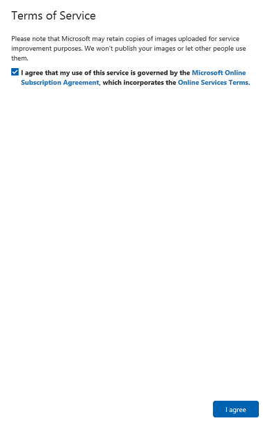
第一次登入之後,系統會提示您輸入 服務條款 面板。 按兩下複選框以 同意條款。 然後按兩下 [我同意]。
您已同意條款,您現在位於 [我的專案 ] 區段中。 按兩下 [ 新增專案]。
![顯示選取 [新增專案的位置] 的螢幕快照。](images/azurelabs-lab310-04.png)
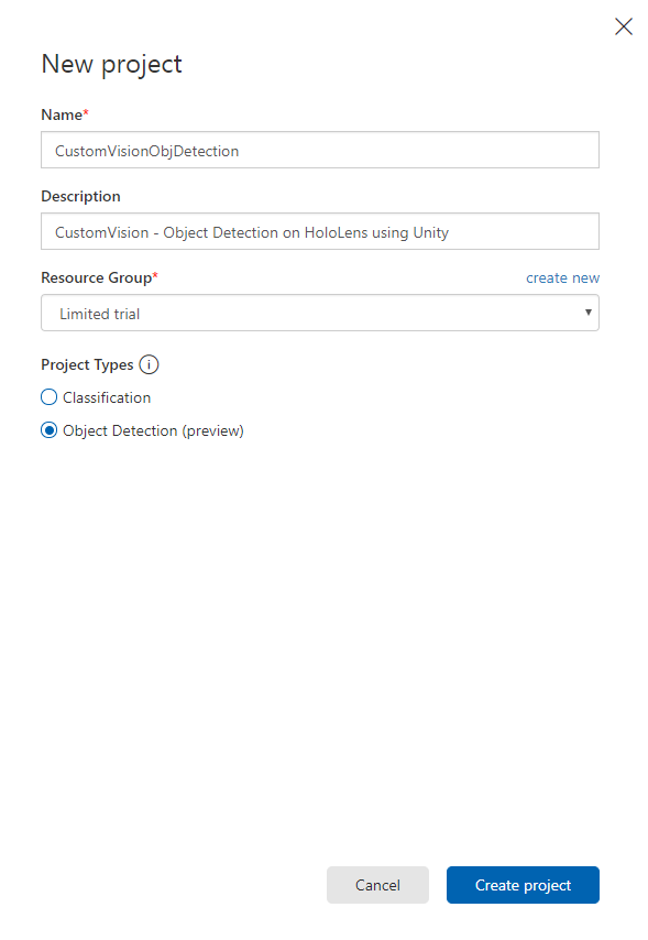
索引標籤會出現在右側,這會提示您指定專案的一些欄位。
插入項目的名稱
插入專案的描述 (選擇性)
選擇 資源群組 或建立新的群組。 資源群組提供一種方式來監視、控制存取、布建和管理 Azure 資產集合的計費。 建議您保留與單一專案相關聯的所有 Azure 服務 (,例如這些課程) 在通用資源群組底下) 。
注意
將 項目類型 設定為 物件偵測 (預覽) 。
完成後,按兩下 [建立專案],系統會將您重新導向至 [自訂視覺 服務專案] 頁面。
第 2 章 - 訓練您的 自訂視覺 專案
一旦在 自訂視覺 入口網站中,您的主要目標是將專案定型,以辨識影像中的特定物件。
您想要讓應用程式辨識的每個物件,至少需要15個 (15個) 影像。 您可以使用本課程所提供的影像, (一系列的杯子) 。
若要訓練您的 自訂視覺 專案:
按兩下 [標記] 旁的+按鈕。
![顯示 [標記] 旁 [+] 按鈕的螢幕快照。](images/azurelabs-lab310-06.png)
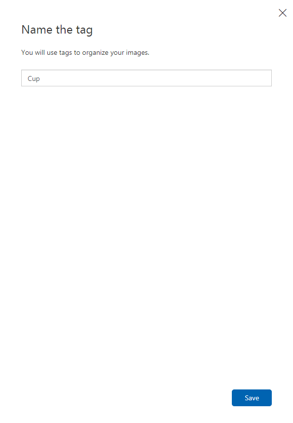
新增標記 的名稱 ,以用來將影像與 產生關聯。 在此範例中,我們會使用杯子影像進行辨識,因此已為此 Cup 命名標記。 完成之後,按兩下 [ 儲存 ]。
您會注意到您的 標籤 已新增 (您可能需要重載頁面,才能顯示) 。

按兩下頁面中央的 [ 新增影像 ]。
按兩下 [ 瀏覽本機檔案],然後流覽至您想要上傳一個物件的影像,至少為15 (15) 。
提示
您可以一次選取數個影像來上傳。

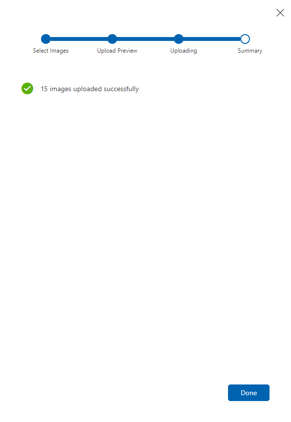
選取您想要訓練專案的所有影像之後,請按 [上傳檔案 ]。 檔案將會開始上傳。 確認上傳之後,按兩下 [ 完成]。
此時,您的影像會上傳,但未加上標記。
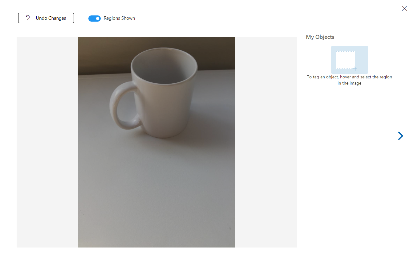
若要標記您的影像,請使用滑鼠。 當您將滑鼠停留在影像上時,選取範圍醒目提示將協助您自動繪製物件周圍的選取範圍。 如果不正確,您可以自行繪製。 這可藉由按住滑鼠左鍵並拖曳選取區域來包含您的物件來完成。

在影像中選取對象之後,小提示會要求您 新增區域標籤。 選取您先前建立的標籤 ('Cup',在上述範例中) ,或如果您要新增更多標籤,請在 中輸入 ,然後按兩下 [+ (加) ] 按鈕。
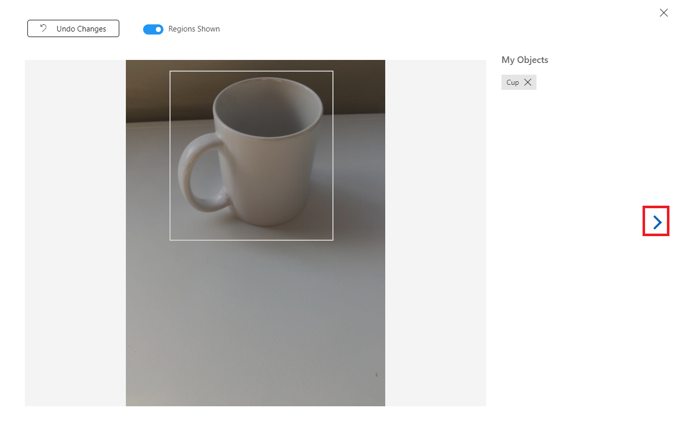
若要標記下一個影像,您可以按下刀鋒視窗右邊的箭號,或按兩下刀鋒視窗右上角的 X 來關閉標籤鋒視窗 (,) 然後按下一個影像。 當您準備好下一個映射之後,請重複相同的程式。 請針對您上傳的所有影像執行此動作,直到標記它們為止。
注意
您可以在相同的影像中選取數個物件,如下所示:
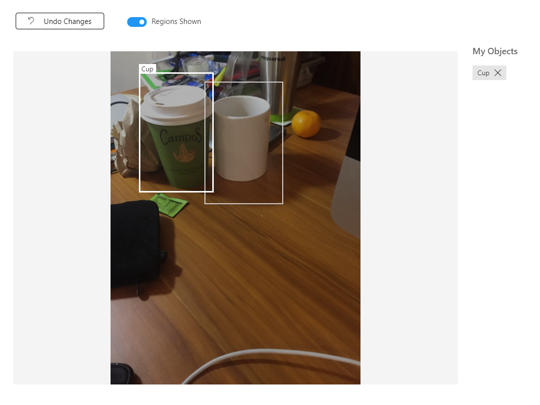
標記全部之後,請按兩下畫面左側 的已標記 按鈕,以顯示已標記的影像。
![醒目提示 [已標記] 按鈕的螢幕快照。](images/azurelabs-lab310-16.png)
您現在已準備好訓練您的服務。 按兩下 [ 定型] 按鈕,第一個訓練反復專案將會開始。
![醒目提示 [訓練] 按鈕的螢幕快照。](images/azurelabs-lab310-17.png)
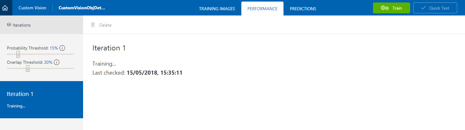
建置之後,您將可以看到兩個稱為 [建立預設 ] 和 [ 預測 URL] 的按鈕。 按兩下 [ 先設定預設值 ],然後按兩下 [ 預測URL]。
![醒目提示 [建立預設] 按鈕的螢幕快照。](images/azurelabs-lab310-19.png)
注意
從這個提供的端點會設定 為 [反復 專案] 標示為預設值。 因此,如果您稍後進行新的 反覆 專案並將其更新為預設值,則不需要變更程序代碼。
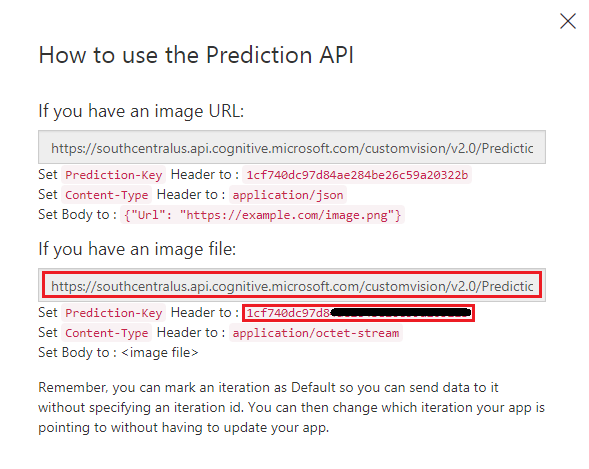
按兩下 [預測 URL] 之後,請開啟 [記事本],然後複製並貼上 URL (也稱為 Prediction-Endpoint) 和服務 預測密鑰,以便稍後在程式代碼中需要時加以擷取。
第 3 章 - 設定 Unity 專案
以下是使用混合實境進行開發的一般設定,因此是其他專案的良好範本。
開啟 Unity ,然後按兩下 [ 新增]。
![醒目提示 [新增] 按鈕的螢幕快照。](images/azurelabs-lab310-21.png)
您現在必須提供 Unity 項目名稱。 插入 CustomVisionObjDetection。 請確定項目類型設定為 3D,並將 [位置 ] 設定為適合您 (記住,更接近根目錄的較佳) 。 然後按兩下 [ 建立專案]。
![顯示專案詳細數據和選取 [建立專案的位置] 的螢幕快照。](images/azurelabs-lab310-22.png)
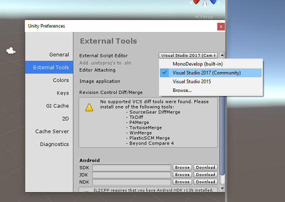
開啟 Unity 時,值得檢查預設 腳本編輯器 已設定為 Visual Studio。 移至 [編輯>喜好 設定],然後從新視窗流覽至 [外部工具]。 將 外部腳本編輯器 變更為 Visual Studio。 關閉 [喜好設定] 視窗。
接下來,移至 [檔案>建置設定],並將 [平臺] 切換為 [通用 Windows 平台],然後按兩下 [切換平臺] 按鈕。
![醒目提示 [切換平臺] 按鈕的螢幕快照。](images/azurelabs-lab310-24.png)
在相同的 [ 建置設定 ] 視窗中,確定已設定下列專案:
目標裝置 已設定為 HoloLens
組建類型 設定為 D3D
SDK 已設定為 [最新安裝]
Visual Studio 版本 設定為 [最新安裝]
[建置並執行 ] 設定為 [ 本機計算機]
建置 設定中的其餘設定現在應該保留為預設值。
![顯示 [建置設定] 組態選項的螢幕快照。](images/azurelabs-lab310-25.png)
在相同的 [ 組建設定 ] 視窗中,按兩下 [ 播放程式設定 ] 按鈕,這會在 Inspector 所在的空間中開啟相關的面板。
在此面板中,必須驗證一些設定:
在 [ 其他設定] 索引 標籤中:
腳本運行時間版本 應該是 實驗 性 (.NET 4.6 對等) ,這會觸發重新啟動編輯器的需求。
腳本後端 應該是 .NET。
API 相容性層級 應該是 .NET 4.6。
![顯示 [API 兼容性層級] 選項設定為 .NET 4.6 的螢幕快照。](images/azurelabs-lab310-26.png)
在 [ 發佈設定] 索引標籤的 [ 功能] 底下,檢查:
InternetClient
網路攝影機
SpatialPerception
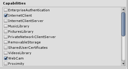 螢幕快照。
螢幕快照。![顯示 [功能] 組態選項下半部的](images/azurelabs-lab310-28.png) 螢幕快照。
螢幕快照。
進一步在面板下方的 [XR 設定] (找到 [發佈設定]) ,然後勾選 [支援的虛擬實境],然後確定已新增 Windows Mixed Reality SDK。

回到 [建置設定], Unity C# 專案 不再呈現灰色:勾選此旁的複選框。
關閉 [組建設定] 視窗。
在 編輯器中,按兩下 [ 編輯>項目設定>圖形]。
![顯示已選取 [圖形] 選單選項的螢幕快照。](images/azurelabs-lab310-30.png)
在 [偵測器] 面板中 ,[ 圖形設定 ] 將會開啟。 向下卷動直到您看到名為 Always Include 著色器的陣列為止。 在此範例中,藉由將 Size 變數增加一個 (來新增位置,這是 8 個,因此我們將其設為 9) 。 新的位置會出現在陣列的最後一個位置,如下所示:
![醒目提示 [一律包含著色器] 陣列的螢幕快照。](images/azurelabs-lab310-31.png)
在位置中,按兩下位置旁的小型目標圓形,以開啟著色器清單。 尋找 舊版著色器/透明/擴散 著色器,然後按兩下。

第 4 章 - 匯入 CustomVisionObjDetection Unity 套件
針對本課程,您會提供名為 Azure-MR-310.unitypackage 的 Unity 資產套件。
[TIP]Unity 支援的任何物件,包括整個場景,都可以封裝成 .unitypackage 檔案,並在其他專案中匯出/匯入。 這是在不同 Unity 專案之間行動資產的最安全且最有效率的方式。
您可以 在這裡找到您需要下載的 Azure-MR-310 套件。
在 Unity 儀錶板前面,單擊畫面頂端功能表中的 [ 資產 ],然後按兩下 [ 匯入套件 > 自定義套件]。
![醒目提示 [自定義套件] 選單選項的螢幕快照。](images/azurelabs-lab310-33.png)
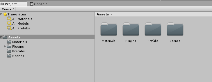
使用檔案選擇器來選取 Azure-MR-310.unitypackage 套件,然後按兩下 [ 開啟]。 此資產的元件清單會顯示給您。 按兩下 [ 匯 入] 按鈕以確認匯入。
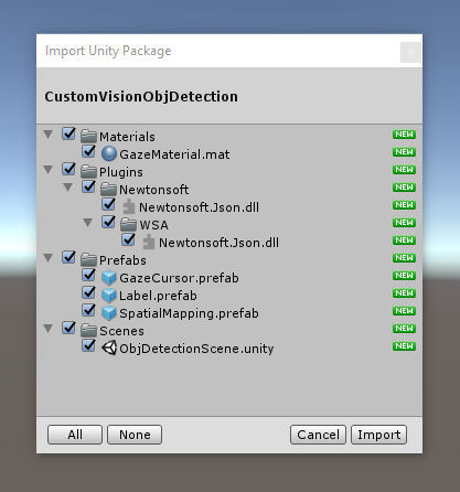
一旦完成匯入,您就會注意到套件中的資料夾現在已新增至 您的 Assets 資料夾。 這種資料夾結構通常適用於 Unity 專案。
[材質] 資料夾包含註視游標所使用的材質。
Plugins 資料夾包含程式代碼用來還原串行化服務 Web 回應的 Newtonsoft DLL。 這兩個 (2) 資料夾和子資料夾中所包含的不同版本,都必須允許 Unity 編輯器和 UWP 組建同時使用和建置連結庫。
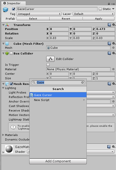
Prefabs 資料夾包含場景中所包含的預製專案。 這些是:
- GazeCursor,這是應用程式中使用的數據指標。 將搭配 SpatialMapping 預製專案一起運作,以能夠在實體物件之上的場景中放置。
- Label,這是 UI 對象,用來在必要時在場景中顯示物件標籤。
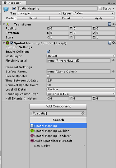
- SpatialMapping,這是可讓應用程式使用 Microsoft HoloLens 空間追蹤來建立虛擬地圖的物件。
目前包含本課程預先建置場景的 Scenes 資料夾。
在 [專案面板] 中開啟 Scenes 資料夾,然後按兩下 ObjDetectionScene,以載入您將用於本課程的場景。

注意
未包含任何程式代碼,您將遵循此課程撰寫程式代碼。
第 5 章 - 建立 CustomVisionAnalyser 類別。
此時,您已準備好撰寫一些程序代碼。 您將從 CustomVisionAnalyser 類別開始。
注意
對 自訂視覺 服務的呼叫,在如下所示的程式代碼中,會使用 自訂視覺 REST API 進行。 透過使用此方式,您將瞭解如何實作及利用此 API (,以瞭解如何在您自己的) 上實作類似專案。 請注意,Microsoft 提供 自訂視覺 SDK,也可用來呼叫服務。 如需詳細資訊,請流覽 自訂視覺 SDK 一文。
此類別負責:
載入擷取為位元組數位的最新影像。
將位元組數位送至 Azure 自訂視覺 服務實例進行分析。
以 JSON 字串形式接收回應。
將回應還原串行化,並將產生的 預測 傳遞至 SceneOrganiser 類別,這會負責響應的顯示方式。
若要建立此類別:
以滑鼠右鍵按兩下 [資產資料夾],位於 [項目面板] 中,然後按兩下 [ 建立>資料夾]。 呼叫 [腳稿] 資料夾。
![顯示如何建立 [腳稿] 資料夾的螢幕快照。](images/azurelabs-lab310-37.png)
按兩下新建立的資料夾,以開啟它。
在資料夾內按下滑鼠右鍵,然後按兩下 [ 建立>C# 腳本]。 將腳本命名為 CustomVisionAnalyser。
按兩下新的 CustomVisionAnalyser 腳本,以使用 Visual Studio 加以開啟。
請確定您在檔案頂端參考了下列命名空間:
using Newtonsoft.Json;
using System.Collections;
using System.IO;
using UnityEngine;
using UnityEngine.Networking;
在 CustomVisionAnalyser 類別中,新增下列變數:
    /// <summary>
    /// Unique instance of this class
    /// </summary>
    public static CustomVisionAnalyser Instance;

    /// <summary>
    /// Insert your prediction key here
    /// </summary>
    private string predictionKey = "- Insert your key here -";

    /// <summary>
    /// Insert your prediction endpoint here
    /// </summary>
    private string predictionEndpoint = "Insert your prediction endpoint here";

    /// <summary>
    /// Bite array of the image to submit for analysis
    /// </summary>
    [HideInInspector] public byte[] imageBytes;
注意
請務必將 服務預測密鑰 插入 predictionKey 變數,並將 您的 Prediction-Endpoint 插入 predictionEndpoint 變數。 您 稍早在步驟 14 第 2 章中將這些內容複製到 [記事本]。
現在必須新增 Awake () 的程式代碼,以初始化 Instance 變數:
    /// <summary>
    /// Initializes this class
    /// </summary>
    private void Awake()
    {
        // Allows this instance to behave like a singleton
        Instance = this;
    }
將協同程式 (與靜態 GetImageAsByteArray () 方法一起新增) ,這會取得 ImageCapture 類別所擷取之影像分析的結果。
注意
在 AnalysisImageCapture 協同程式中,您尚未建立 的 SceneOrganiser 類別呼叫。 因此,請保留這些行的批注。
    /// <summary>
    /// Call the Computer Vision Service to submit the image.
    /// </summary>
    public IEnumerator AnalyseLastImageCaptured(string imagePath)
    {
        Debug.Log("Analyzing...");

        WWWForm webForm = new WWWForm();

        using (UnityWebRequest unityWebRequest = UnityWebRequest.Post(predictionEndpoint, webForm))
        {
            // Gets a byte array out of the saved image
            imageBytes = GetImageAsByteArray(imagePath);

            unityWebRequest.SetRequestHeader("Content-Type", "application/octet-stream");
            unityWebRequest.SetRequestHeader("Prediction-Key", predictionKey);

            // The upload handler will help uploading the byte array with the request
            unityWebRequest.uploadHandler = new UploadHandlerRaw(imageBytes);
            unityWebRequest.uploadHandler.contentType = "application/octet-stream";

            // The download handler will help receiving the analysis from Azure
            unityWebRequest.downloadHandler = new DownloadHandlerBuffer();

            // Send the request
            yield return unityWebRequest.SendWebRequest();

            string jsonResponse = unityWebRequest.downloadHandler.text;

            Debug.Log("response: " + jsonResponse);

            // Create a texture. Texture size does not matter, since
            // LoadImage will replace with the incoming image size.
            //Texture2D tex = new Texture2D(1, 1);
            //tex.LoadImage(imageBytes);
            //SceneOrganiser.Instance.quadRenderer.material.SetTexture("_MainTex", tex);

            // The response will be in JSON format, therefore it needs to be deserialized
            //AnalysisRootObject analysisRootObject = new AnalysisRootObject();
            //analysisRootObject = JsonConvert.DeserializeObject<AnalysisRootObject>(jsonResponse);

            //SceneOrganiser.Instance.FinaliseLabel(analysisRootObject);
        }
    }

    /// <summary>
    /// Returns the contents of the specified image file as a byte array.
    /// </summary>
    static byte[] GetImageAsByteArray(string imageFilePath)
    {
        FileStream fileStream = new FileStream(imageFilePath, FileMode.Open, FileAccess.Read);

        BinaryReader binaryReader = new BinaryReader(fileStream);

        return binaryReader.ReadBytes((int)fileStream.Length);
    }
刪除 Start () 和 Update () 方法,因為不會使用這些方法。
在返回 Unity 之前,請務必先將變更儲存在 Visual Studio 中。
重要
如先前所述,別擔心可能會有錯誤的程式代碼,因為您很快就會提供進一步的類別,這會修正這些類別。
第 6 章 - 建立 CustomVisionObjects 類別
您將會建立的類別現在是 CustomVisionObjects 類別。
此腳本包含其他類別用來串行化和還原串行化對 自訂視覺 服務所做的呼叫的一些物件。
若要建立此類別:
在 [腳本 ] 資料夾內按下滑鼠右鍵,然後按兩下 [ 建立>C# 腳本]。 呼叫 CustomVisionObjects 腳本。
按兩下新的 CustomVisionObjects 命令本,以使用 Visual Studio 加以開啟。
請確定您在檔案頂端參考了下列命名空間:
using System;
using System.Collections.Generic;
using UnityEngine;
using UnityEngine.Networking;
刪除 CustomVisionObjects 類別內的 Start () 和 Update () 方法,此類別現在應該是空的。
警告
請務必仔細遵循下一個指示。 如果您在 CustomVisionObjects 類別中放置新的類別宣告,您將會在 第 10 章中收到編譯錯誤,指出找不到 AnalysisRootObject 和 BoundingBox 。
在 CustomVisionObjects 類別之外新增下列類別。 Newtonsoft 連結庫會使用這些物件來串行化和還原串行化回應數據:
// The objects contained in this script represent the deserialized version
// of the objects used by this application

/// <summary>
/// Web request object for image data
/// </summary>
class MultipartObject : IMultipartFormSection
{
    public string sectionName { get; set; }

    public byte[] sectionData { get; set; }

    public string fileName { get; set; }

    public string contentType { get; set; }
}

/// <summary>
/// JSON of all Tags existing within the project
/// contains the list of Tags
/// </summary>
public class Tags_RootObject
{
    public List<TagOfProject> Tags { get; set; }
    public int TotalTaggedImages { get; set; }
    public int TotalUntaggedImages { get; set; }
}

public class TagOfProject
{
    public string Id { get; set; }
    public string Name { get; set; }
    public string Description { get; set; }
    public int ImageCount { get; set; }
}

/// <summary>
/// JSON of Tag to associate to an image
/// Contains a list of hosting the tags,
/// since multiple tags can be associated with one image
/// </summary>
public class Tag_RootObject
{
    public List<Tag> Tags { get; set; }
}

public class Tag
{
    public string ImageId { get; set; }
    public string TagId { get; set; }
}

/// <summary>
/// JSON of images submitted
/// Contains objects that host detailed information about one or more images
/// </summary>
public class ImageRootObject
{
    public bool IsBatchSuccessful { get; set; }
    public List<SubmittedImage> Images { get; set; }
}

public class SubmittedImage
{
    public string SourceUrl { get; set; }
    public string Status { get; set; }
    public ImageObject Image { get; set; }
}

public class ImageObject
{
    public string Id { get; set; }
    public DateTime Created { get; set; }
    public int Width { get; set; }
    public int Height { get; set; }
    public string ImageUri { get; set; }
    public string ThumbnailUri { get; set; }
}

/// <summary>
/// JSON of Service Iteration
/// </summary>
public class Iteration
{
    public string Id { get; set; }
    public string Name { get; set; }
    public bool IsDefault { get; set; }
    public string Status { get; set; }
    public string Created { get; set; }
    public string LastModified { get; set; }
    public string TrainedAt { get; set; }
    public string ProjectId { get; set; }
    public bool Exportable { get; set; }
    public string DomainId { get; set; }
}

/// <summary>
/// Predictions received by the Service
/// after submitting an image for analysis
/// Includes Bounding Box
/// </summary>
public class AnalysisRootObject
{
    public string id { get; set; }
    public string project { get; set; }
    public string iteration { get; set; }
    public DateTime created { get; set; }
    public List<Prediction> predictions { get; set; }
}

public class BoundingBox
{
    public double left { get; set; }
    public double top { get; set; }
    public double width { get; set; }
    public double height { get; set; }
}

public class Prediction
{
    public double probability { get; set; }
    public string tagId { get; set; }
    public string tagName { get; set; }
    public BoundingBox boundingBox { get; set; }
}
在返回 Unity 之前,請務必先將變更儲存在 Visual Studio 中。
第 7 章 - 建立 SpatialMapping 類別
這個類別會在場景中設定 空間對應碰撞器 ,以便能夠偵測虛擬對象與實際對象之間的衝突。
若要建立此類別:
在 [腳本 ] 資料夾內按下滑鼠右鍵,然後按兩下 [ 建立>C# 腳本]。 呼叫 Script SpatialMapping。
按兩下新的 SpatialMapping 腳本,以使用 Visual Studio 開啟它。
請確定您在 SpatialMapping 類別上方參考了下列命名空間:
using UnityEngine;
using UnityEngine.XR.WSA;
然後,在 SpatialMapping 類別中,於 Start () 方法上方新增下列變數:
    /// <summary>
    /// Allows this class to behave like a singleton
    /// </summary>
    public static SpatialMapping Instance;

    /// <summary>
    /// Used by the GazeCursor as a property with the Raycast call
    /// </summary>
    internal static int PhysicsRaycastMask;

    /// <summary>
    /// The layer to use for spatial mapping collisions
    /// </summary>
    internal int physicsLayer = 31;

    /// <summary>
    /// Creates environment colliders to work with physics
    /// </summary>
    private SpatialMappingCollider spatialMappingCollider;
新增 Awake () 和 Start () :
    /// <summary>
    /// Initializes this class
    /// </summary>
    private void Awake()
    {
        // Allows this instance to behave like a singleton
        Instance = this;
    }

    /// <summary>
    /// Runs at initialization right after Awake method
    /// </summary>
    void Start()
    {
        // Initialize and configure the collider
        spatialMappingCollider = gameObject.GetComponent<SpatialMappingCollider>();
        spatialMappingCollider.surfaceParent = this.gameObject;
        spatialMappingCollider.freezeUpdates = false;
        spatialMappingCollider.layer = physicsLayer;

        // define the mask
        PhysicsRaycastMask = 1 << physicsLayer;

        // set the object as active one
        gameObject.SetActive(true);
    }
刪除 Update () 方法。
在返回 Unity 之前,請務必先將變更儲存在 Visual Studio 中。
第 8 章 - 建立 GazeCursor 類別
這個類別負責使用在上一章中建立的 SpatialMappingCollider,在真實空間的正確位置設定游標。
若要建立此類別:
在 [腳本 ] 資料夾內按下滑鼠右鍵,然後按兩下 [ 建立>C# 腳本]。 呼叫 腳本 GazeCursor
按兩下新的 GazeCursor 腳本,以使用 Visual Studio 開啟它。
請確定您在 GazeCursor 類別上方參考了下列命名空間:
using UnityEngine;然後在 GazeCursor 類別中,於 Start () 方法上方新增下列變數。
    /// <summary>
    /// The cursor (this object) mesh renderer
    /// </summary>
    private MeshRenderer meshRenderer;
使用下列程序代碼更新 Start () 方法:
    /// <summary>
    /// Runs at initialization right after the Awake method
    /// </summary>
    void Start()
    {
        // Grab the mesh renderer that is on the same object as this script.
        meshRenderer = gameObject.GetComponent<MeshRenderer>();

        // Set the cursor reference
        SceneOrganiser.Instance.cursor = gameObject;
        gameObject.GetComponent<Renderer>().material.color = Color.green;

        // If you wish to change the size of the cursor you can do so here
        gameObject.transform.localScale = new Vector3(0.01f, 0.01f, 0.01f);
    }
使用下列程序代碼 更新 Update () 方法:
    /// <summary>
    /// Update is called once per frame
    /// </summary>
    void Update()
    {
        // Do a raycast into the world based on the user's head position and orientation.
        Vector3 headPosition = Camera.main.transform.position;
        Vector3 gazeDirection = Camera.main.transform.forward;

        RaycastHit gazeHitInfo;
        if (Physics.Raycast(headPosition, gazeDirection, out gazeHitInfo, 30.0f, SpatialMapping.PhysicsRaycastMask))
        {
            // If the raycast hit a hologram, display the cursor mesh.
            meshRenderer.enabled = true;
            // Move the cursor to the point where the raycast hit.
            transform.position = gazeHitInfo.point;
            // Rotate the cursor to hug the surface of the hologram.
            transform.rotation = Quaternion.FromToRotation(Vector3.up, gazeHitInfo.normal);
        }
        else
        {
            // If the raycast did not hit a hologram, hide the cursor mesh.
            meshRenderer.enabled = false;
        }
    }
注意
別擔心找不到 SceneOrganiser 類別的錯誤,您將在下一章中加以建立。
在返回 Unity 之前,請務必先將變更儲存在 Visual Studio 中。
第 9 章 - 建立 SceneOrganiser 類別
此類別將會:
藉由將適當的元件附加至 主要相機來設定主要相機 。
偵測到物件時,它會負責計算其在真實世界中的位置,並使用適當的標籤名稱將標籤放在其附近。
若要建立此類別:
在 [腳本 ] 資料夾內按下滑鼠右鍵,然後按兩下 [ 建立>C# 腳本]。 將腳本命名為 SceneOrganiser。
按兩下新的 SceneOrganiser 腳稿,以使用 Visual Studio 加以開啟。
請確定您在 SceneOrganiser 類別上方參考了下列命名空間:
using System.Collections.Generic;
using System.Linq;
using UnityEngine;
然後在 SceneOrganiser 類別中,於 Start () 方法上方新增下列變數:
    /// <summary>
    /// Allows this class to behave like a singleton
    /// </summary>
    public static SceneOrganiser Instance;

    /// <summary>
    /// The cursor object attached to the Main Camera
    /// </summary>
    internal GameObject cursor;

    /// <summary>
    /// The label used to display the analysis on the objects in the real world
    /// </summary>
    public GameObject label;

    /// <summary>
    /// Reference to the last Label positioned
    /// </summary>
    internal Transform lastLabelPlaced;

    /// <summary>
    /// Reference to the last Label positioned
    /// </summary>
    internal TextMesh lastLabelPlacedText;

    /// <summary>
    /// Current threshold accepted for displaying the label
    /// Reduce this value to display the recognition more often
    /// </summary>
    internal float probabilityThreshold = 0.8f;

    /// <summary>
    /// The quad object hosting the imposed image captured
    /// </summary>
    private GameObject quad;

    /// <summary>
    /// Renderer of the quad object
    /// </summary>
    internal Renderer quadRenderer;
刪除 Start () 和 Update () 方法。
在變數底下,新增 Awake () 方法,以初始化 類別並設定場景。
    /// <summary>
    /// Called on initialization
    /// </summary>
    private void Awake()
    {
        // Use this class instance as singleton
        Instance = this;

        // Add the ImageCapture class to this Gameobject
        gameObject.AddComponent<ImageCapture>();

        // Add the CustomVisionAnalyser class to this Gameobject
        gameObject.AddComponent<CustomVisionAnalyser>();

        // Add the CustomVisionObjects class to this Gameobject
        gameObject.AddComponent<CustomVisionObjects>();
    }
新增 PlaceAnalysisLabel () 方法,此方法會將場景中的標籤 具現化 (此時使用者) 看不到該標籤。 它也會將四邊形 (放在影像的位置) 不可見,並與真實世界重疊。 這很重要,因為分析後從服務擷取的方塊座標會追蹤回這個四邊形,以判斷對象在真實世界中的近似位置。
    /// <summary>
    /// Instantiate a Label in the appropriate location relative to the Main Camera.
    /// </summary>
    public void PlaceAnalysisLabel()
    {
        lastLabelPlaced = Instantiate(label.transform, cursor.transform.position, transform.rotation);
        lastLabelPlacedText = lastLabelPlaced.GetComponent<TextMesh>();
        lastLabelPlacedText.text = "";
        lastLabelPlaced.transform.localScale = new Vector3(0.005f,0.005f,0.005f);

        // Create a GameObject to which the texture can be applied
        quad = GameObject.CreatePrimitive(PrimitiveType.Quad);
        quadRenderer = quad.GetComponent<Renderer>() as Renderer;
        Material m = new Material(Shader.Find("Legacy Shaders/Transparent/Diffuse"));
        quadRenderer.material = m;

        // Here you can set the transparency of the quad. Useful for debugging
        float transparency = 0f;
        quadRenderer.material.color = new Color(1, 1, 1, transparency);

        // Set the position and scale of the quad depending on user position
        quad.transform.parent = transform;
        quad.transform.rotation = transform.rotation;

        // The quad is positioned slightly forward in font of the user
        quad.transform.localPosition = new Vector3(0.0f, 0.0f, 3.0f);

        // The quad scale as been set with the following value following experimentation,
        // to allow the image on the quad to be as precisely imposed to the real world as possible
        quad.transform.localScale = new Vector3(3f, 1.65f, 1f);
        quad.transform.parent = null;
    }
新增 FinaliseLabel () 方法。 下列為其負責的項目:
- 以最高信賴度設定具有預測標籤的標籤文字。
- 在四邊形物件上呼叫 周框方塊 的計算,並置於先前的位置,並將標籤放在場景中。
- 使用Raycast向 周框方塊調整標籤深度,這應該與真實世界中的物件碰撞。
- 重設擷取程式,讓使用者擷取另一個映像。
    /// <summary>
    /// Set the Tags as Text of the last label created.
    /// </summary>
    public void FinaliseLabel(AnalysisRootObject analysisObject)
    {
        if (analysisObject.predictions != null)
        {
            lastLabelPlacedText = lastLabelPlaced.GetComponent<TextMesh>();
            // Sort the predictions to locate the highest one
            List<Prediction> sortedPredictions = new List<Prediction>();
            sortedPredictions = analysisObject.predictions.OrderBy(p => p.probability).ToList();
            Prediction bestPrediction = new Prediction();
            bestPrediction = sortedPredictions[sortedPredictions.Count - 1];

            if (bestPrediction.probability > probabilityThreshold)
            {
                quadRenderer = quad.GetComponent<Renderer>() as Renderer;
                Bounds quadBounds = quadRenderer.bounds;

                // Position the label as close as possible to the Bounding Box of the prediction
                // At this point it will not consider depth
                lastLabelPlaced.transform.parent = quad.transform;
                lastLabelPlaced.transform.localPosition = CalculateBoundingBoxPosition(quadBounds, bestPrediction.boundingBox);

                // Set the tag text
                lastLabelPlacedText.text = bestPrediction.tagName;

                // Cast a ray from the user's head to the currently placed label, it should hit the object detected by the Service.
                // At that point it will reposition the label where the ray HL sensor collides with the object,
                // (using the HL spatial tracking)
                Debug.Log("Repositioning Label");
                Vector3 headPosition = Camera.main.transform.position;
                RaycastHit objHitInfo;
                Vector3 objDirection = lastLabelPlaced.position;
                if (Physics.Raycast(headPosition, objDirection, out objHitInfo, 30.0f,   SpatialMapping.PhysicsRaycastMask))
                {
                    lastLabelPlaced.position = objHitInfo.point;
                }
            }
        }
        // Reset the color of the cursor
        cursor.GetComponent<Renderer>().material.color = Color.green;

        // Stop the analysis process
        ImageCapture.Instance.ResetImageCapture();
    }
新增 CalculateBoundingBoxPosition () 方法,其裝載許多計算,以轉譯從服務擷取的 周框方塊 坐標,並在四邊形上按比例重新建立這些座標。
    /// <summary>
    /// This method hosts a series of calculations to determine the position
    /// of the Bounding Box on the quad created in the real world
    /// by using the Bounding Box received back alongside the Best Prediction
    /// </summary>
    public Vector3 CalculateBoundingBoxPosition(Bounds b, BoundingBox boundingBox)
    {
        Debug.Log($"BB: left {boundingBox.left}, top {boundingBox.top}, width {boundingBox.width}, height {boundingBox.height}");

        double centerFromLeft = boundingBox.left + (boundingBox.width / 2);
        double centerFromTop = boundingBox.top + (boundingBox.height / 2);
        Debug.Log($"BB CenterFromLeft {centerFromLeft}, CenterFromTop {centerFromTop}");

        double quadWidth = b.size.normalized.x;
        double quadHeight = b.size.normalized.y;
        Debug.Log($"Quad Width {b.size.normalized.x}, Quad Height {b.size.normalized.y}");

        double normalisedPos_X = (quadWidth * centerFromLeft) - (quadWidth/2);
        double normalisedPos_Y = (quadHeight * centerFromTop) - (quadHeight/2);

        return new Vector3((float)normalisedPos_X, (float)normalisedPos_Y, 0);
    }
請務必先將變更儲存在 Visual Studio中,再返回 Unity。
重要
繼續之前,請先開啟 CustomVisionAnalyser 類別,然後在 [分析][LastImageCaptured] () 方法中 取消批注 下列幾行:
// Create a texture. Texture size does not matter, since
// LoadImage will replace with the incoming image size.
Texture2D tex = new Texture2D(1, 1);
tex.LoadImage(imageBytes);
SceneOrganiser.Instance.quadRenderer.material.SetTexture("_MainTex", tex);

// The response will be in JSON format, therefore it needs to be deserialized
AnalysisRootObject analysisRootObject = new AnalysisRootObject();
analysisRootObject = JsonConvert.DeserializeObject<AnalysisRootObject>(jsonResponse);

SceneOrganiser.Instance.FinaliseLabel(analysisRootObject);
注意
別擔心 ImageCapture 類別 「找不到」訊息,您將在下一章中建立它。
第 10 章 - 建立 ImageCapture 類別
您要建立的下一個類別是 ImageCapture 類別。
此類別負責:
- 使用 HoloLens 相機擷取影像,並將其儲存在 [應用程式 ] 資料夾中。
- 處理使用者的 點選 手勢。
若要建立此類別:
移至您先前建立的 Scripts 資料夾。
在資料夾內按下滑鼠右鍵,然後按兩下 [建立>C# 腳本]。 將腳本命名為 ImageCapture。
按兩下新的 ImageCapture 腳稿,以使用 Visual Studio 加以開啟。
以下欄內容取代檔案頂端的命名空間:
using System;
using System.IO;
using System.Linq;
using UnityEngine;
using UnityEngine.XR.WSA.Input;
using UnityEngine.XR.WSA.WebCam;
然後在 ImageCapture 類別的 Start () 方法上方新增下列變數:
    /// <summary>
    /// Allows this class to behave like a singleton
    /// </summary>
    public static ImageCapture Instance;

    /// <summary>
    /// Keep counts of the taps for image renaming
    /// </summary>
    private int captureCount = 0;

    /// <summary>
    /// Photo Capture object
    /// </summary>
    private PhotoCapture photoCaptureObject = null;

    /// <summary>
    /// Allows gestures recognition in HoloLens
    /// </summary>
    private GestureRecognizer recognizer;

    /// <summary>
    /// Flagging if the capture loop is running
    /// </summary>
    internal bool captureIsActive;

    /// <summary>
    /// File path of current analysed photo
    /// </summary>
    internal string filePath = string.Empty;
現在必須新增 Awake () 和 Start () 方法的程序代碼:
    /// <summary>
    /// Called on initialization
    /// </summary>
    private void Awake()
    {
        Instance = this;
    }

    /// <summary>
    /// Runs at initialization right after Awake method
    /// </summary>
    void Start()
    {
        // Clean up the LocalState folder of this application from all photos stored
        DirectoryInfo info = new DirectoryInfo(Application.persistentDataPath);
        var fileInfo = info.GetFiles();
        foreach (var file in fileInfo)
        {
            try
            {
                file.Delete();
            }
            catch (Exception)
            {
                Debug.LogFormat("Cannot delete file: ", file.Name);
            }
        }

        // Subscribing to the Microsoft HoloLens API gesture recognizer to track user gestures
        recognizer = new GestureRecognizer();
        recognizer.SetRecognizableGestures(GestureSettings.Tap);
        recognizer.Tapped += TapHandler;
        recognizer.StartCapturingGestures();
    }
實作會在點選手勢發生時呼叫的處理程式:
    /// <summary>
    /// Respond to Tap Input.
    /// </summary>
    private void TapHandler(TappedEventArgs obj)
    {
        if (!captureIsActive)
        {
            captureIsActive = true;

            // Set the cursor color to red
            SceneOrganiser.Instance.cursor.GetComponent<Renderer>().material.color = Color.red;

            // Begin the capture loop
            Invoke("ExecuteImageCaptureAndAnalysis", 0);
        }
    }
重要
當游標為 綠色時,表示相機可用來拍攝影像。 當游標為 紅色時,表示相機忙碌中。
新增應用程式用來啟動映像擷取程式並儲存映像的方法:
    /// <summary>
    /// Begin process of image capturing and send to Azure Custom Vision Service.
    /// </summary>
    private void ExecuteImageCaptureAndAnalysis()
    {
        // Create a label in world space using the ResultsLabel class
        // Invisible at this point but correctly positioned where the image was taken
        SceneOrganiser.Instance.PlaceAnalysisLabel();

        // Set the camera resolution to be the highest possible
        Resolution cameraResolution = PhotoCapture.SupportedResolutions.OrderByDescending
            ((res) => res.width * res.height).First();
        Texture2D targetTexture = new Texture2D(cameraResolution.width, cameraResolution.height);

        // Begin capture process, set the image format
        PhotoCapture.CreateAsync(true, delegate (PhotoCapture captureObject)
        {
            photoCaptureObject = captureObject;

            CameraParameters camParameters = new CameraParameters
            {
                hologramOpacity = 1.0f,
                cameraResolutionWidth = targetTexture.width,
                cameraResolutionHeight = targetTexture.height,
                pixelFormat = CapturePixelFormat.BGRA32
            };

            // Capture the image from the camera and save it in the App internal folder
            captureObject.StartPhotoModeAsync(camParameters, delegate (PhotoCapture.PhotoCaptureResult result)
            {
                string filename = string.Format(@"CapturedImage{0}.jpg", captureCount);
                filePath = Path.Combine(Application.persistentDataPath, filename);
                captureCount++;
                photoCaptureObject.TakePhotoAsync(filePath, PhotoCaptureFileOutputFormat.JPG, OnCapturedPhotoToDisk);
            });
        });
    }
新增將在擷取相片時呼叫的處理程式,以及何時準備好進行分析。 結果接著會傳遞至 CustomVisionAnalyser 進行分析。
    /// <summary>
    /// Register the full execution of the Photo Capture.
    /// </summary>
    void OnCapturedPhotoToDisk(PhotoCapture.PhotoCaptureResult result)
    {
        try
        {
            // Call StopPhotoMode once the image has successfully captured
            photoCaptureObject.StopPhotoModeAsync(OnStoppedPhotoMode);
        }
        catch (Exception e)
        {
            Debug.LogFormat("Exception capturing photo to disk: {0}", e.Message);
        }
    }

    /// <summary>
    /// The camera photo mode has stopped after the capture.
    /// Begin the image analysis process.
    /// </summary>
    void OnStoppedPhotoMode(PhotoCapture.PhotoCaptureResult result)
    {
        Debug.LogFormat("Stopped Photo Mode");

        // Dispose from the object in memory and request the image analysis
        photoCaptureObject.Dispose();
        photoCaptureObject = null;

        // Call the image analysis
        StartCoroutine(CustomVisionAnalyser.Instance.AnalyseLastImageCaptured(filePath));
    }

    /// <summary>
    /// Stops all capture pending actions
    /// </summary>
    internal void ResetImageCapture()
    {
        captureIsActive = false;

        // Set the cursor color to green
        SceneOrganiser.Instance.cursor.GetComponent<Renderer>().material.color = Color.green;

        // Stop the capture loop if active
        CancelInvoke();
    }
請務必先將變更儲存在 Visual Studio中,再返回 Unity。
第 11 章 - 在場景中設定腳本
既然您已撰寫此專案所需的所有程序代碼,就可以在場景中設定腳本,並在預製專案上設定腳本,讓它們正常運作。
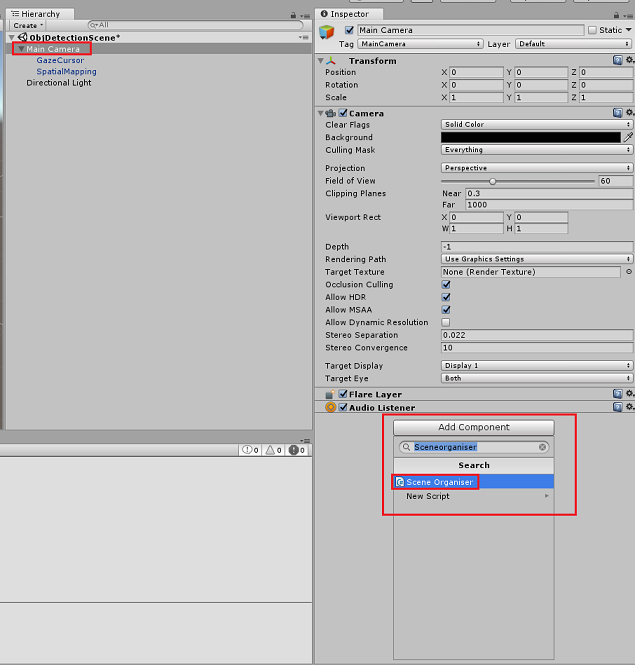
在 Unity 編輯器的 [ 階層] 面板中,選取 [主相機]。
在 [ 偵測器面板] 中,選取 [主要相機 ],按兩下 [ 新增元件],然後搜尋 SceneOrganiser 腳本,然後按兩下以新增它。
在 [專案面板] 中,開啟 Prefabs 資料夾,將標籤預製專案拖曳至 [卷標] 空白參考目標輸入區域,在您剛新增至主相機的 SceneOrganiser 腳本中,如下圖所示:

在 [階層] 面板中,選取主相機的 GazeCursor 子系。
在 [偵測器] 面板中,選取 [GazeCursor ],按兩下 [ 新增元件],然後搜尋 GazeCursor 腳本,然後按兩下以新增它。
同樣地,在 [階層面板] 中,選取主相機的 SpatialMapping 子系。
在 [偵測器] 面板中,選取 SpatialMapping ,單擊 [ 新增元件],然後搜尋 SpatialMapping 腳本,然後按兩下以新增它。
您尚未設定的其餘腳本將會在運行時間期間,由 SceneOrganiser 腳本中的程式代碼新增。
第 12 章 - 建置之前
若要執行應用程式的完整測試,您必須將它側載至您的 Microsoft HoloLens。
在您這麼做之前,請確定:
第 3 章中所述的所有設定都已正確設定。
腳本 SceneOrganiser 會附加至 主要相機 物件。
GazeCursor 腳本會附加至 GazeCursor 物件。
SpatialMapping 腳本會附加至 SpatialMapping 物件。
在第 5 章的步驟 6:
- 請確定您將 服務預測金鑰 插入 predictionKey 變數中。
- 您已將 預測端點 插入 predictionEndpoint 類別。
第 13 章 - 建置 UWP 解決方案並側載您的應用程式
您現在已準備好將應用程式建置為UWP解決方案,您將能夠部署到 Microsoft HoloLens。 若要開始建置程式:
移至 [檔案 > 組建設定]。
刻度 Unity C# 專案。
按兩下 [ 新增開啟的場景]。 這會將目前開啟的場景新增至組建。
![醒目提示 [新增開啟場景] 按鈕的螢幕快照。](images/azurelabs-lab310-42.png)
按一下 [建置]。 Unity 會啟動 檔案總管 視窗,您需要在其中建立,然後選取要建置應用程式的資料夾。 立即建立該資料夾,並將它命名為 應用程式。 然後在選取 [應用程式 ] 資料夾的情況下,按兩下 [ 選取資料夾]。
Unity 會開始將專案建置至 [應用程式 ] 資料夾。
一旦 Unity 完成建置 (可能需要一些時間) ,它會在組建的位置開啟 檔案總管 視窗, (檢查您的任務列,因為它可能不一定會出現在您的視窗上方,但會通知您新增視窗) 。
若要部署至 Microsoft HoloLens,您需要該裝置的IP位址 (進行遠端部署) ,並確保其也已設定開發人員模式。 作法如下:
在戴上 HoloLens 的同時,開啟 [ 設定]。
移至 網路 & 因特網>Wi-Fi>進階選項
請注意 IPv4 位址。
接下來,流覽回 [設定],然後流覽回 [更新開發人員的安全性 & 安全性>]
設定 [開啟開發人員模式]。
流覽至新的 Unity 組建 (應用程式 資料夾) ,並使用 Visual Studio 開啟方案檔。
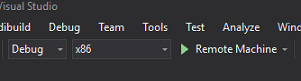
在 [方案組態] 中,選取 [ 偵錯]。
在 [解決方案平臺] 中,選取 [x86] [遠端計算機]。 在此案例中,系統會提示您插入遠端裝置的IP位址, (Microsoft HoloLens,在此案例中表示) 。
移至 [ 建置 ] 功能表,然後按兩下 [ 部署解決方案 ] 將應用程式側載至 HoloLens。
您的應用程式現在應該會出現在您的 Microsoft HoloLens 上安裝的應用程式清單中,準備好要啟動!
若要使用應用程式:
- 查看您已使用 Azure 自訂視覺 服務定型的物件、物件偵測,以及使用點選手勢。
- 如果成功偵測到物件,則會以標籤名稱顯示世界空間標籤 文字 。
重要
每次擷取相片並將其傳送至服務時,您可以返回 [服務] 頁面,並使用新擷取的影像重新定型服務。 一開始,您可能也必須更正 周框方 塊,以更精確並重新定型服務。
注意
當 Unity 中的 Microsoft HoloLens 感測器和/或 SpatialTrackingComponent 無法放置與真實世界物件相關的適當碰撞器時,放置的卷標文字可能不會出現在物件附近。 如果是這種情況,請嘗試在不同的介面上使用應用程式。
您的 自訂視覺 物件偵測應用程式
恭喜,您已建置混合實境應用程式,利用 Azure 自訂視覺、物件偵測 API,可從影像辨識物件,然後在 3D 空間中提供該物件的近似位置。
額外練習
練習 1
新增至文字標籤,使用半透明 Cube 將實際物件包裝在 3D 周框方塊中。
練習 2
訓練您的 自訂視覺 服務以辨識更多物件。
練習 3
辨識物件時播放音效。
練習 4
使用 API 以應用程式正在分析的相同影像來重新定型您的服務,因此為了讓服務更精確, (同時進行預測和訓練) 。