Implementing an OCSP Responder: Part V High Availability
Chris Here Again. In the four previous parts of this series we covered the basics of OCSP, as well as the steps required to prepare the CA and implement the OCSP Responder. In this section I would like to talk about how to implement a High Availability OCSP Configuration.
There are two major pieces in implementing the High Availability Configuration. The first step is to add the OCSP Responders to what is called an Array. When OCSP Responders are configured in an Array, the configuration of the OCSP responders can be easily maintained, so that all Responders in the Array have the same configuration. The configuration of the Array Controller is used as the baseline configuration that is then applied to other members of the Array.
The second piece is to load balance the OCSP Responders. Load balancing of the OCSP responders is what actually provides fault tolerance. I am going to demonstrate using the built in Windows Network Load Balancing feature of Windows Server 2008. You can of course use a third party hardware load balancer if you wish. In this example, we are going to deploy two OCSP Servers in a highly available configuration.
Firewall Exceptions
In Windows Server 2008 the Windows Firewall is enabled by default. Depending on the requirements of your enterprise, you may have the firewall in its default state, you may have it turned off, or you may have a custom configuration.
If you are unfamiliar with Windows Firewall with Advanced Security, you may want to review Windows Firewall with Advanced Security and IPSEC, which has links to a variety of sources for learning about as well configuring and implementing the Windows Firewall with Advanced Security. The document includes a link on how to deploy firewall settings with Group Policy.
The Windows Firewall with Advanced Security there are three types of profiles:
- Domain . Windows automatically identifies networks on which it can authenticate access to the domain controller for the domain to which the computer is joined in this category. No other networks can be placed in this category.
- Public . Other than domain networks, all networks are initially categorized as public. Networks that represent direct connections to the Internet or are in public places, such as airports and coffee shops should be left public.
- Private . A network will only be categorized as private if a user or application identifies the network as private. Only networks located behind a NAT device (preferably a hardware firewall) should be identified as private networks. Users will likely want to identify home or small business networks as private.
https://technet.microsoft.com/en-us/library/cc748991(WS.10).aspx
In a higher security environment you may want to configure this setting for a specific profile. For example inside an enterprise you may want to enable the rule just for the Domain Profile.
In this example when we configure the rules, we are configuring them for Any profile, which will allow the responder to be managed regardless of which profile is applied.
When you install the OCSP Role the following Inbound Rules will be configured on the Windows Firewall:
World Wide Web Services (HTTP Traffic-IN)
World Wide Web Services (HTTPS Traffic-IN)
Also, the following Outbound Rule will be enabled:
Online Responder Service (TCP-Out)
These rules allow the OCSP Responder to receive the OCSP requests from the client and to respond to the OCSP clients.
You will also need to enable the following rules to manage the OCSP Responders as well as allowing the OCSP Responder to sync the configuration with the Array Controller:
Online Responder Service DCOM-In
Online Responder Service RPC-In
To enable the rules, open the Windows Firewall with Advanced Security MMC (WF.msc) and click on Inbound Rules. Find the rule, right click on the rule and select Enable Rule from the context menu.
You should perform this action on every OCSP Responder that will be a member of the array. A more scalable solution is to place all of the OCSP Responders in a common OU, and use group policy to maintain a consistent configuration.
CA Preparation
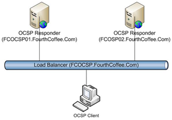
In Part II of this series we discussed preparing the certificate authorities for use with the OCSP Responder. One of the configuration steps was to configure the Authority Information Access (AIA) extensions with the OCSP Extension that included the URL that points to the OCSP Responder. When configuring an OCSP Responder in a Load Balanced Configuration you will need to specify the name of the Load Balancer. Below is a diagram of the OCSP Infrastructure that I will walk through implementing in this blog posting. Notice that the name of the two OCSP Responders are FCOCSP01.FourthCoffee.Com and FCOCSP02.FourthCoffee.com. You will also notice that I have decided to assign the name of FCOCSP.FourthCoffee.Com to the NLB Cluster. Since I want clients to access the load balancer and let the load balancer determine which OCSP Responder that the OCSP Requests goes to, I must specify FCOCSP.FourthCoffee.Com in the OCSP URI.
DNS Configuration
As mentioned above, you will want OCSP clients to send the OCSP Requests to the Load Balancer. This allows the Load Balancer to balance requests, this is especially important if one of the OCSP Responders is offline. To ensure that clients can resolve the DNS name of the cluster you will want to register the hostname in DNS.
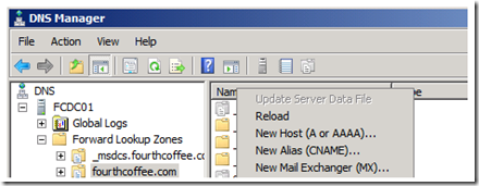
To register the A record for the NLB cluster in DNS, perform the following steps:
1. Open up the DNS Manager MMC (dnsmgmt.msc)
2. Right click on the appropriate zone and select New Host (A or AAAA)… from the context menu.
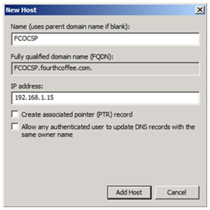
3. In the New Host dialogue box enter the hostname that will be used for the NLB Cluster, and enter the appropriate IP address. You can provide additional configuration such as Create associated (PTR) record if appropriate for your environment.
Configuring OCSP Responder Array
In the upcoming section we will configure two OCSP Responders in an array. The purpose of configuring an array is to maintain the same configuration between OCSP Responders. It is important to be aware of what Revocation Configurations you will be supporting with the Array. In the case of Revocation Configurations that support Enterprise CAs and that are configured to automatically enroll for an OCSP signing certificate, the process is somewhat transparent since the responders added to the array will automatically request the OCSP signing certificate. In the case of Revocation Configuration’s that support Standalone CA’s, an OCSP Signing certificate will need to be manually requested, installed and configured. And of course the OCSP Responder can support both types of Revocation Configurations on the same responder.
OCSP Responder Array Setup
Prerequisites: The Windows Firewall has been configured as shown in the Firewall Exceptions sections above.
Steps:
1. OCSP Signing Certificate must of course be available on the Enterprise CA that the array is going to provide revocation information for. All OCSP Responders that are going to be members of the Array must have Read and Enroll permissions for the OCSP Signing Certificate. Alternatively if the Array is going to support a Revocation Configuration for a Standalone CA, the OCSP signing certificate will need to be installed manually. Remember to give read permission to the Private Key for any OCSP Signing certificates that are installed manually. If you are unfamiliar with this process, instructions for giving the Network Service read permissions to the private key of the OCSP signing certificate are available in Part I of this series.
2. Configure the OCSP Responder that will become the Array Controller. For guidance on deploying an OCSP Responder please see Part III and Part IV of this series.
3. Configure the first OCSP Responder as an Array Controller.
4. Add additional OCSP Responders to the array.
Note: if using OCSP Responders on hyper-V guests, see extra steps here on how to configure NLB virtual guests.
I will be covering the final two steps as the other steps are covered elsewhere in this Blog Series.
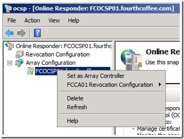
1. In the Online Responder Management Console, expand Array Configuration. Select the Responder that you wish to make the Array Controller, right click on the responder name, and select Set as Array Controller from the context menu.
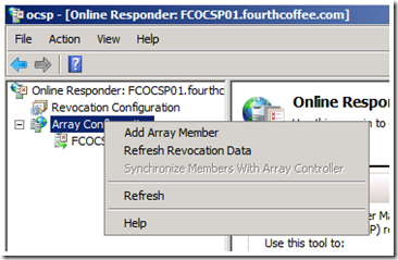
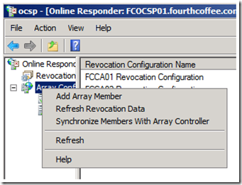
2. To add an OCSP Responder to the array, right click on Array Configuration, and select Add Array Member from the context menu.
3. You will then receive the Select Computer dialog box. Click on the Browse… button.
4. Enter the name of the OCSP Responder that you wish to add, and click on the Check Names button.
5. Once the computer name of the OCSP Responder has been resolved, click OK.
6. The Select Computer dialogue box will now be populated with FQDN of the computer that is hosting the Online Responder, click OK.
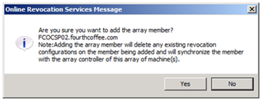
7. You will then be prompted to confirm that you wish to add the array member. This dialogue box will give you one last chance to abort before the configuration of the OCSP Responder is overwritten with the configuration of the Array Controller. Click Yes to continue.
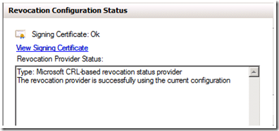
8. To verify the configuration expand Array Configuration in the OCSP MMC and select the name of the Responder that was just added. The Revocation Configuration Status should be the same as illustrated in the figure below.
Note: If you are using a manually installed certificate, such as from a Standalone CA, you will receive the error in the figure below.
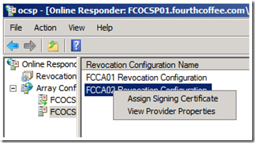
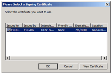
To rectify this issue you will need to manually assign the certificate after it is installed in the Local Machine Store. Expand Array Configuration, click on the name of the OCSP Server that was just added to the Array, and Right click on the Revocation Configuration that will be using a manually assigned signing certificate. Select Assign Signing Certificate from the context menu.
Select the appropriate certificate, and click OK.
You will then get the error listed below. This error simply indicates that the OCSP Responder has not yet retrieved revocation information, so it can not verify that the configuration is correct.
If you would like to clear this error, Right click on Array Configuration and select Refresh Revocation Data.
Installing the Network Load Balancing Feature
Before you install and configure the NLB cluster, there are some key items you will need to know ahead of time:
- What is the IP address you are going to assign to the NLB cluster?
- What DNS name you are going to associate with this cluster?
Before you can configure the NLB Cluster, you must first install the Network Load Balancing feature on all of the OCSP Responders that will be a member of the NLB cluster.
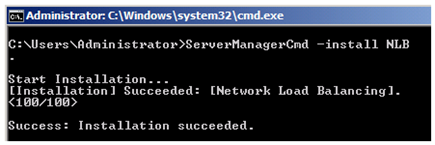
To install the NLB feature, open a command prompt, and type ServerManagerCmd –install NLB, as illustrated below.
Configuring the NLB Cluster
1. Once the Network Load Balancing feature is installed, open the Network Load Balancing Manager.
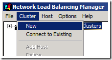
2. Select Cluster from the Menu Bar, and then select New. This will start the New Cluster Wizard.
3. Enter the hostname of the first node and click Connect, then click Next.
4. This will open the Host Parameters page of the New Cluster Wizard. Accept the defaults and click Next.
5. Next on the Cluster IP address page of the Wizard, click Add…
6. Here you will add the IP address and subnet mask of the Load Balancer. After you enter the network information, click OK.
7. Then click Next.
8. On the Cluster Parameters page add the FQDN of the cluster in the Full Internet Name text box. Configure the Cluster Operation Mode as appropriate for your environment. In this example I have selected Unicast.
9. On the Port Rules Page click Finish.
Add Nodes to the cluster
For each node that you would like to add to the NLB cluster you will need to perform the following steps.
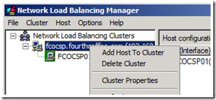
1. Expand Network Load Balancing Clusters in the Network Load Balancing Manager. Right click on the name of the cluster and select Add Host to Cluster from the context menu. This will start the Add Host to Cluster Wizard.
2. On the Connect Page of the Wizard, enter the hostname of the node you wish to add to the cluster and click Connect.
3. On the Host Parameters page click Next.
4. On the Port Rules page of the Wizard click Finish.
Conclusion
In this posting we covered implementing a highly available OCSP Responder. In the next part of this series I will be covering how to configure clients to obtain revocation information from an OCSP Responder that is not listed in the OCSP URI of the certificate.
Implementing an OCSP responder: Part I Introducing OCSP
Implementing an OCSP responder: Part II Preparing Certificate Authorities
Implementing an OCSP responder: Part III Configuring OCSP for use with Enterprise CAs
Implementing an OCSP responder: Part IV Configuring OCSP for use with Standalone CAs
Implementing an OCSP Responder: Part V High Availability
Implementing an OCSP Responder: Part VI Configuring Custom OCSP URIs via Group Policy
-Chris ‘Tickle Fight’ Delay

