Commission the AKS cluster
The packet core instances in the Azure Private 5G Core service run on an Arc-enabled Azure Kubernetes Service (AKS) cluster on an Azure Stack Edge (ASE) device. This how-to guide shows how to commission the AKS cluster on ASE so that it's ready to deploy a packet core instance.
Important
This procedure must only be used for Azure Private 5G Core. AKS on ASE is not supported for other services.
Prerequisites
- Complete the prerequisite tasks for deploying a private mobile network.
- You will need Owner permission on the resource group for your Azure Stack Edge resource.
Note
Make a note of the Azure Stack Edge's resource group. The AKS cluster and custom location, created in this procedure, must belong to this resource group.
- Review Azure Stack Edge virtual machine sizing to ensure your ASE has enough space available to commission the cluster.
Configure Kubernetes for Azure Private MEC on the Azure Stack Edge device
These steps modify the Kubernetes cluster on the Azure Stack Edge device to optimize it for Azure Private MEC workloads.
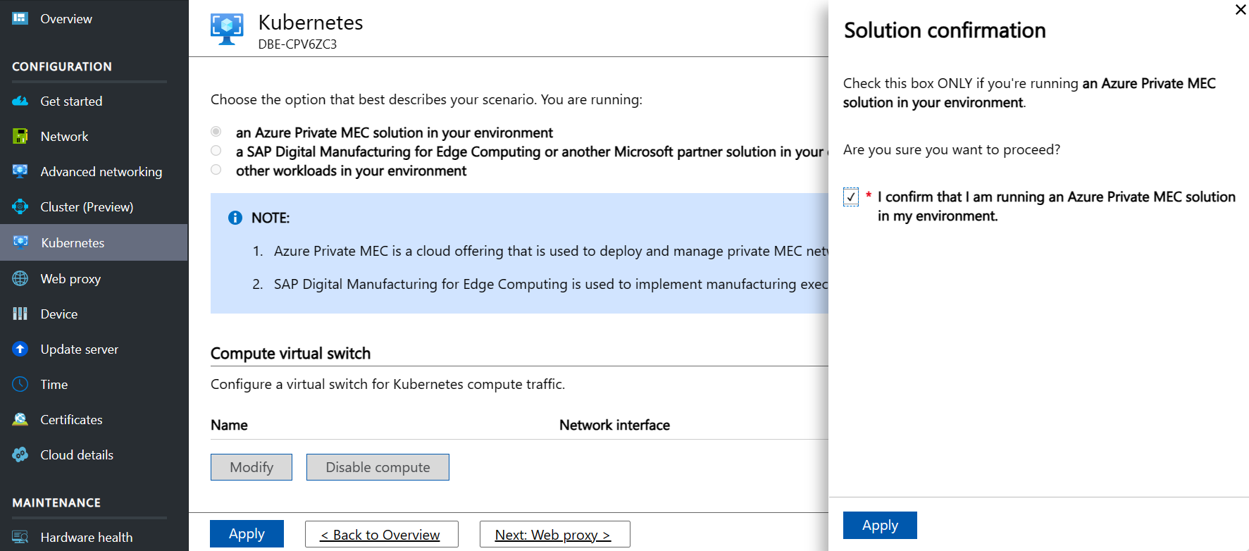
- In the local UI, select Kubernetes in the left-hand menu.
- Under Choose the option that best describes your scenario, select an Azure Private MEC solution in your environment.
- On the Workload confirmation popup, select I confirm I am running Azure Private MEC in my environment, and click Apply to close the popup.
- Click Apply to save the changes.
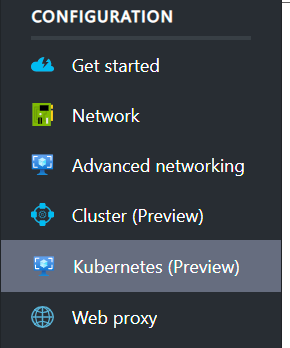
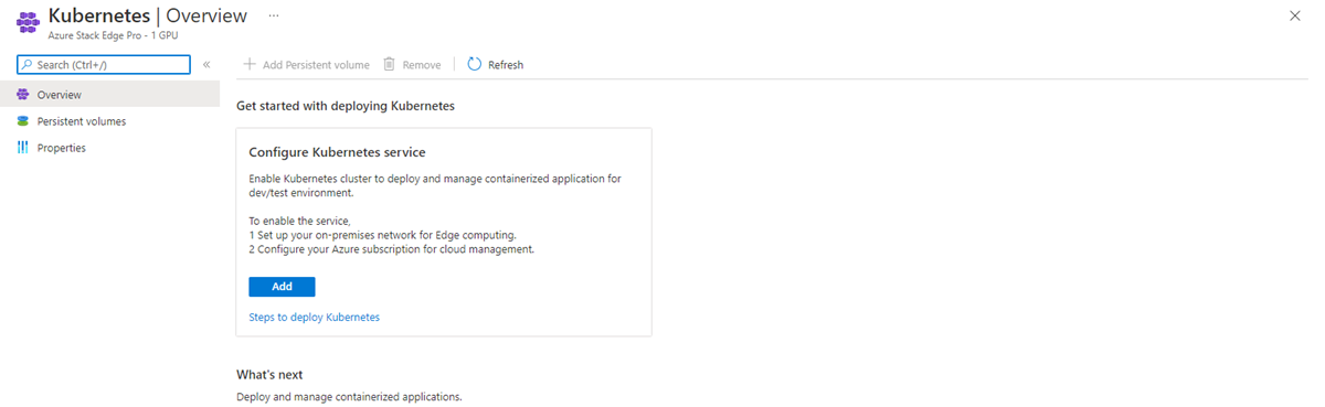
Once you've applied these changes, you should see an updated option in the local UI – Kubernetes becomes Kubernetes (Preview) as shown in the following image.
If you go to the Azure portal and navigate to your Azure Stack Edge resource, you should see an Azure Kubernetes Service option. You'll set up the Azure Kubernetes Service in Start the cluster and set up Arc.

Set up advanced networking
You now need to configure virtual switches and virtual networks on those switches. You'll use the Advanced networking section of the Azure Stack Edge local UI to do this task.
You can input all the settings on this page before selecting Apply at the bottom to apply them all at once.
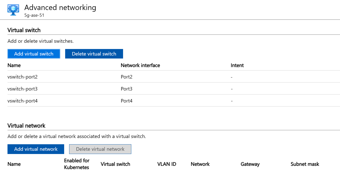
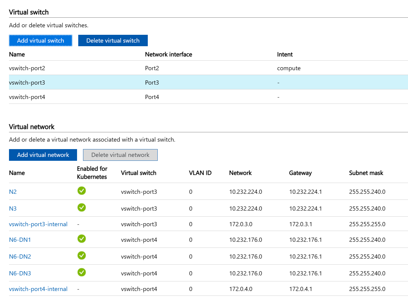
Configure three virtual switches. There must be a virtual switch associated with each port before the next step. The virtual switches may already be present if you have other virtual network functions (VNFs) set up. Select Add virtual switch and fill in the side panel appropriately for each switch before selecting Modify to save that configuration.
- Create a virtual switch on the port that should have compute enabled (the management port). We recommend using the format vswitch-portX, where X is the number of the port. For example, create vswitch-port2 on port 2.
- Create a virtual switch on port 3 with the name vswitch-port3.
- Create a virtual switch on port 4 with the name vswitch-port4.
You should now see something similar to the following image:
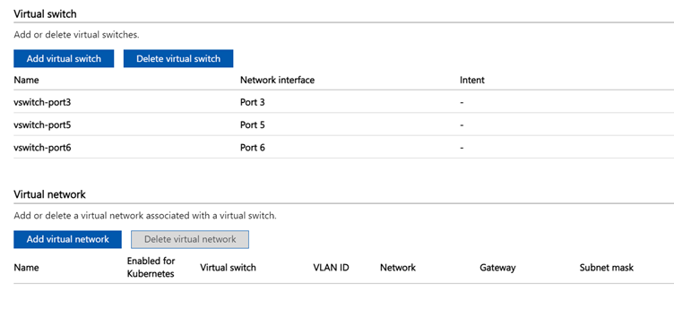
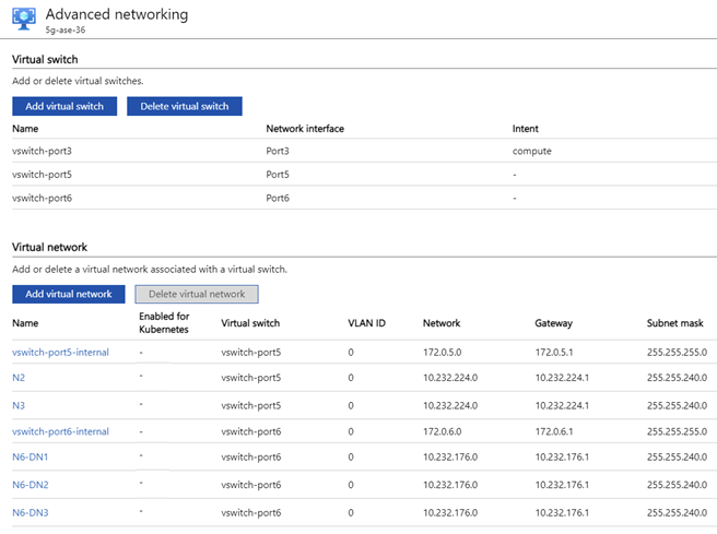
Configure three virtual switches. There must be a virtual switch associated with each port before the next step. The virtual switches may already be present if you have other virtual network functions (VNFs) set up. Select Add virtual switch and fill in the side panel appropriately for each switch before selecting Modify to save that configuration.
- Create a virtual switch on the port that should have compute enabled (the management port). We recommend using the format vswitch-portX, where X is the number of the port. For example, create vswitch-port3 on port 3.
- Create a virtual switch on port 5 with the name vswitch-port5.
- Create a virtual switch on port 6 with the name vswitch-port6.
You should now see something similar to the following image:
Create virtual networks representing the following interfaces (which you allocated subnets and IP addresses for in Allocate subnets and IP addresses):
- Control plane access interface
- User plane access interface
- User plane data interface(s)
You can name these networks yourself, but the name must match what you configure in the Azure portal when deploying Azure Private 5G Core. For example, you can use the names N2, N3 and up to ten N6-DNX (where X is the DN number 1-10 in a multiple DN deployment; or just N6 for a single DN deployment). You can optionally configure each virtual network with a virtual local area network identifier (VLAN ID) to enable layer 2 traffic separation. The following example is for a 5G multi-DN deployment without VLANs.
- Carry out the following procedure three times, plus once for each of the supplementary data networks (twelve times in total if you have the maximum ten data networks):
Important
If you are using port 3 for data networks, we recommend that it is used for the lowest expected load.
- Select Add virtual network and fill in the side panel:
- Virtual switch: select vswitch-port3 for N2, N3 and up to four DNs, and select vswitch-port4 for up to six DNs.
- Name: N2, N3, or N6-DNX (where X is the DN number 1-10).
- VLAN: VLAN ID, or 0 if not using VLANs
- Network and Gateway: Use the correct subnet and gateway for the IP address configured on the ASE port (even if the gateway is not set on the ASE port itself).
- For example, 10.232.44.0/24 and 10.232.44.1
- If the subnet does not have a default gateway, use another IP address in the subnet which will respond to ARP requests (such as one of the RAN IP addresses). If there's more than one gNB connected via a switch, choose one of the IP addresses for the gateway.
- DNS server and DNS suffix should be left blank.
- Select Modify to save the configuration for this virtual network.
- Select Apply at the bottom of the page and wait for the notification (a bell icon) to confirm that the settings have been applied. Applying the settings will take approximately 8 minutes. The page should now look like the following image:
- Select Add virtual network and fill in the side panel:
- Carry out the following procedure three times, plus once for each of the supplementary data networks (twelve times in total if you have the maximum ten data networks):
Important
If you are using port 5 for data networks, we recommend that it is used for the lowest expected load.
- Select Add virtual network and fill in the side panel:
- Virtual switch: select vswitch-port5 for N2, N3 and up to four DNs, and select vswitch-port6 for up to six DNs.
- Name: N2, N3, or N6-DNX (where X is the DN number 1-10).
- VLAN: VLAN ID, or 0 if not using VLANs
- Network and Gateway: Use the correct subnet and gateway for the IP address configured on the ASE port (even if the gateway is not set on the ASE port itself).
- For example, 10.232.44.0/24 and 10.232.44.1
- If the subnet does not have a default gateway, use another IP address in the subnet which will respond to ARP requests (such as one of the RAN IP addresses). If there's more than one gNB connected via a switch, choose one of the IP addresses for the gateway.
- DNS server and DNS suffix should be left blank.
- Select Modify to save the configuration for this virtual network.
- Select Apply at the bottom of the page and wait for the notification (a bell icon) to confirm that the settings have been applied. Applying the settings will take approximately 8 minutes. The page should now look like the following image:
- Select Add virtual network and fill in the side panel:
Add compute and IP addresses
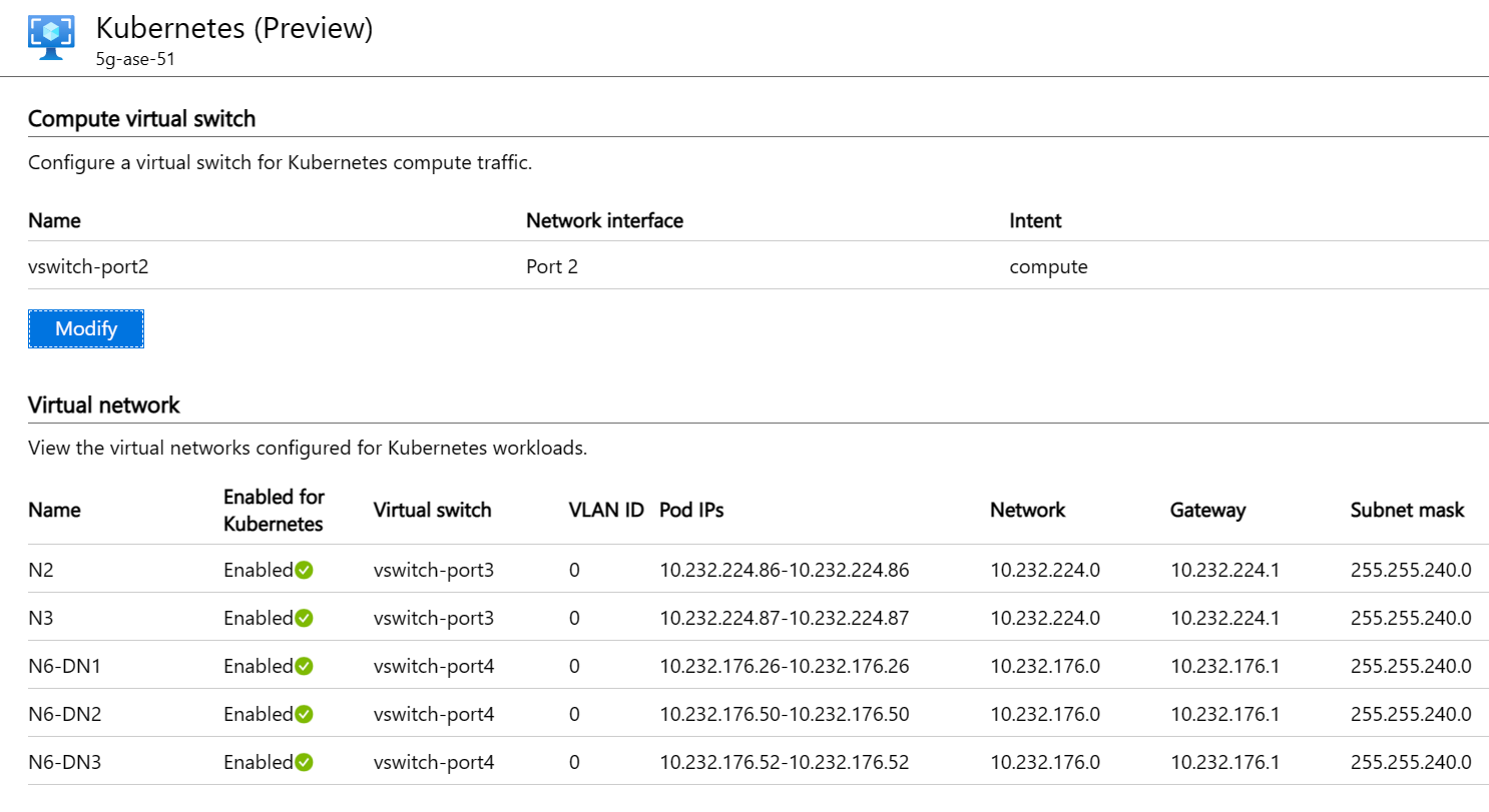
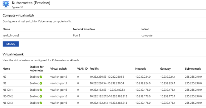
In the local Azure Stack Edge UI, go to the Kubernetes (Preview) page. You'll set up all of the configuration and then apply it once, as you did in Set up Advanced Networking.
- Under Compute virtual switch, select Modify.
- Select the vswitch with compute intent (for example, vswitch-port2)
- Enter six IP addresses in a range for the node IP addresses on the management network.
- Enter one IP address in a range for the service IP address, also on the management network. This will be used for accessing local monitoring tools for the packet core instance.
- Select Modify at the bottom of the panel to save the configuration.
- Under Virtual network, select a virtual network, from N2, N3, N6-DNX (where X is the DN number 1-10). In the side panel:
- Enable the virtual network for Kubernetes and add a pool of IP addresses. Add a range of one IP address for the appropriate address (N2, N3, or N6-DNX as collected earlier). For example, 10.10.10.20-10.10.10.20.
- Repeat for each of the N2, N3, and N6-DNX virtual networks.
- Select Modify at the bottom of the panel to save the configuration.
- Select Apply at the bottom of the page and wait for the settings to be applied. Applying the settings will take approximately 5 minutes.
The page should now look like the following image:
Enable VM management on the ASE
- Access the Azure portal and go to the Azure Stack Edge resource created in the Azure portal.
- Select Edge services.
- Select Virtual machines.
- Select Enable.
Start the cluster and set up Arc
If you're running other VMs on your Azure Stack Edge, we recommend that you stop them now, and start them again once the cluster is deployed. The cluster requires access to specific CPU resources that running VMs may already be using.
Access the Azure portal and go to the Azure Stack Edge resource created in the Azure portal.
To deploy the cluster, select the Kubernetes option and then select the Add button to configure the cluster.
For the Node size, select Standard_F16s_HPN.
Ensure the Arc enabled Kubernetes checkbox is selected.
Select the Change link and enter the Microsoft Entra application Object Id (OID) for the custom location which you obtained from Retrieve the Object ID (OID).
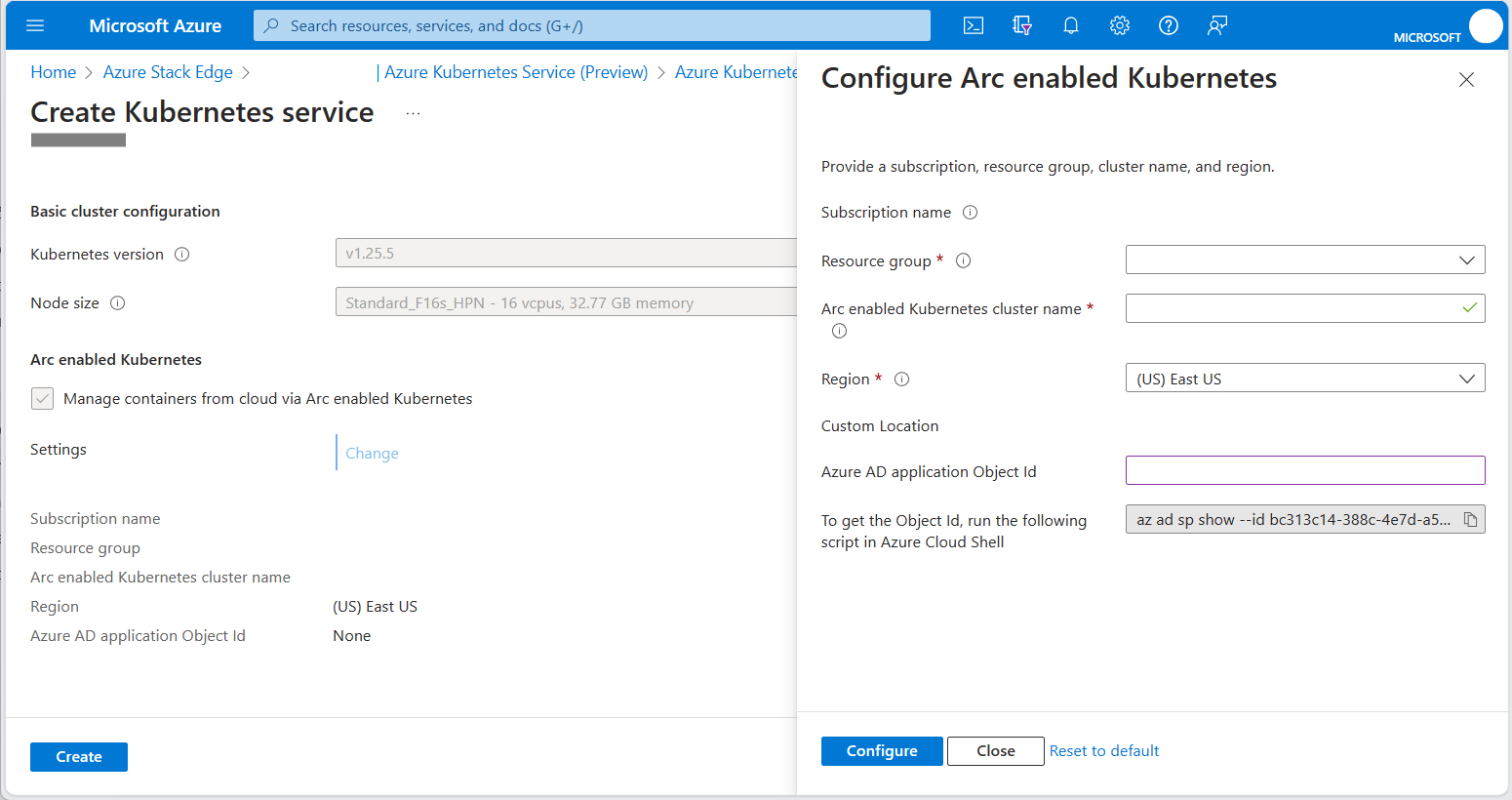
The Arc enabled Kubernetes service is automatically created in the same resource group as your Azure Stack Edge resource. If your Azure Stack Edge resource group is not in a region that supports Azure Private 5G Core, you must change the region.
Click Configure to apply the configuration.
Check the Region and Microsoft Entra application Object Id (OID) fields show the appropriate values, and then click Create.
Work through the prompts to set up the service.
The creation of the Kubernetes cluster takes about 20 minutes. During creation, there may be a critical alarm displayed on the Azure Stack Edge resource. This alarm is expected and should disappear after a few minutes.
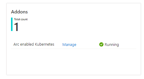
Once deployed, the portal should show Kubernetes service is running on the overview page.
Set up kubectl access
You'll need kubectl access to verify that the cluster has deployed successfully. For read-only kubectl access to the cluster, you can download a kubeconfig file from the ASE local UI. Under Device, select Download config.

The downloaded file is called config.json. This file has permission to describe pods and view logs, but not to access pods with kubectl exec.
Set up portal access
Open your Azure Stack Edge resource in the Azure portal. Go to the Azure Kubernetes Service pane (shown in Start the cluster and set up Arc) and select the Manage link to open the Arc pane.
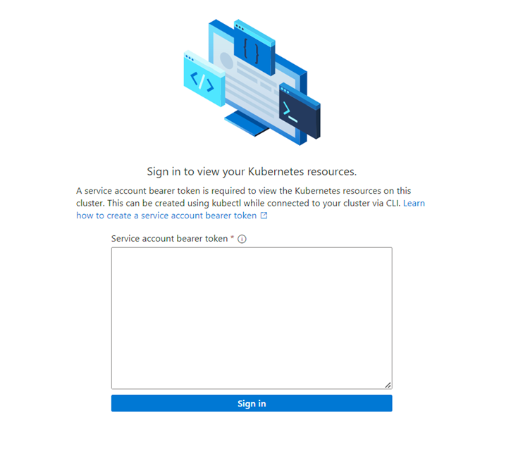
Explore the cluster using the options in the Kubernetes resources (preview) menu:
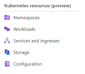
You'll initially be presented with a sign-in request box. The token to use for signing in is obtained from the kubeconfig file retrieved from the local UI in Set up kubectl access. There's a string prefixed by token: near the end of the kubeconfig file. Copy this string into the box in the portal (ensuring you don't have line break characters copied), and select Sign in.
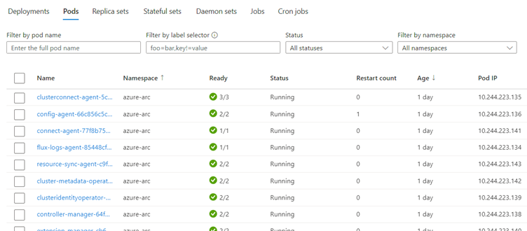
You can now view information about what’s running on the cluster – the following is an example from the Workloads pane:
Verify the cluster configuration
You should verify that the AKS cluster is set up correctly by running the following kubectl commands using the kubeconfig downloaded from the UI in Set up kubectl access:
kubectl get nodes
This command should return two nodes, one named nodepool-aaa-bbb and one named target-cluster-control-plane-ccc.
To view all the running pods, run:
kubectl get pods -A
Additionally, your AKS cluster should now be visible from your Azure Stack Edge resource in the portal.
Collect variables for the Kubernetes extensions
Collect each of the values in the table below.
| Value | Variable name |
|---|---|
| The ID of the Azure subscription in which the Azure resources are deployed. | SUBSCRIPTION_ID |
| The name of the resource group in which the AKS cluster is deployed. This can be found by using the Manage button in the Azure Kubernetes Service pane of the Azure portal. | RESOURCE_GROUP_NAME |
| The name of the AKS cluster resource. This can be found by using the Manage button in the Azure Kubernetes Service pane of the Azure portal. | RESOURCE_NAME |
| The region in which the Azure resources are deployed. This must match the region into which the mobile network will be deployed, which must be one of the regions supported by AP5GC.This value must be the region's code name. | LOCATION |
The name of the Custom location resource to be created for the AKS cluster. This value must start and end with alphanumeric characters, and must contain only alphanumeric characters, - or .. |
CUSTOM_LOCATION |
Install Kubernetes extensions
The Azure Private 5G Core private mobile network requires a custom location and specific Kubernetes extensions that you need to configure using the Azure CLI in Azure Cloud Shell.
Sign in to the Azure CLI using Azure Cloud Shell and select Bash from the dropdown menu.
Set the following environment variables using the required values for your deployment:
SUBSCRIPTION_ID=<subscription ID>
RESOURCE_GROUP_NAME=<resource group name>
LOCATION=<deployment region, for example eastus>
CUSTOM_LOCATION=<custom location for the AKS cluster>
ARC_CLUSTER_RESOURCE_NAME=<resource name>
TEMP_FILE=./tmpfile
Prepare your shell environment:
az account set --subscription "$SUBSCRIPTION_ID"
az extension add --upgrade --name k8s-extension
az extension add --upgrade --name customlocation
Create the Network Function Operator Kubernetes extension:
cat > $TEMP_FILE <<EOF
{
  "helm.versions": "v3",
  "Microsoft.CustomLocation.ServiceAccount": "azurehybridnetwork-networkfunction-operator",
  "meta.helm.sh/release-name": "networkfunction-operator",
  "meta.helm.sh/release-namespace": "azurehybridnetwork",
  "app.kubernetes.io/managed-by": "helm",
  "helm.release-name": "networkfunction-operator",
  "helm.release-namespace": "azurehybridnetwork",
  "managed-by": "helm"
}
EOF
az k8s-extension create \ --name networkfunction-operator \ --cluster-name "$ARC_CLUSTER_RESOURCE_NAME" \ --resource-group "$RESOURCE_GROUP_NAME" \ --cluster-type connectedClusters \ --extension-type "Microsoft.Azure.HybridNetwork" \ --auto-upgrade-minor-version "true" \ --scope cluster \ --release-namespace azurehybridnetwork \ --release-train preview \ --config-settings-file $TEMP_FILECreate the Packet Core Monitor Kubernetes extension:
az k8s-extension create \
--name packet-core-monitor \
--cluster-name "$ARC_CLUSTER_RESOURCE_NAME" \
--resource-group "$RESOURCE_GROUP_NAME" \
--cluster-type connectedClusters \
--extension-type "Microsoft.Azure.MobileNetwork.PacketCoreMonitor" \
--release-train stable \
--auto-upgrade true
Create the custom location:
az customlocation create \
-n "$CUSTOM_LOCATION" \
-g "$RESOURCE_GROUP_NAME" \
--location "$LOCATION" \
--namespace azurehybridnetwork \
--host-resource-id "/subscriptions/$SUBSCRIPTION_ID/resourceGroups/$RESOURCE_GROUP_NAME/providers/Microsoft.Kubernetes/connectedClusters/$ARC_CLUSTER_RESOURCE_NAME" \
--cluster-extension-ids "/subscriptions/$SUBSCRIPTION_ID/resourceGroups/$RESOURCE_GROUP_NAME/providers/Microsoft.Kubernetes/connectedClusters/$ARC_CLUSTER_RESOURCE_NAME/providers/Microsoft.KubernetesConfiguration/extensions/networkfunction-operator"
You should see the new Custom location visible as a resource in the Azure portal within the specified resource group. Using the kubectl get pods -A command (with access to your kubeconfig file) should also show new pods corresponding to the extensions that have been installed. There should be one pod in the azurehybridnetwork namespace, and one in the packet-core-monitor namespace.
Rollback
If you have made an error in the Azure Stack Edge configuration, you can use the portal to remove the AKS cluster (see Deploy Azure Kubernetes service on Azure Stack Edge). You can then modify the settings via the local UI.
Alternatively, you can perform a full reset using the Device Reset blade in the local UI (see Azure Stack Edge device reset and reactivation) and then restart this procedure. In this case, you should also delete any associated resources left in the Azure portal after completing the Azure Stack Edge reset. This will include some or all of the following, depending on how far through the process you are:
- Azure Stack Edge resource
- Autogenerated KeyVault associated with the Azure Stack Edge resource
- Autogenerated StorageAccount associated with the Azure Stack Edge resource
- Azure Kubernetes Cluster (if successfully created)
- Custom location (if successfully created)
Changing ASE configuration after deployment
You may need to update the ASE configuration after deploying the packet core, for example to add or remove an attached data network or to change an IP address. To change ASE configuration, destroy the Custom location and Azure Kubernetes Service resources, make your ASE configuration changes, and then recreate those resources. This allows you to temporarily disconnect the packet core instead of destroying and recreating it, minimizing the reconfiguration needed. You may also need to make equivalent changes to the packet core configuration.
Caution
Your packet core will be unavailable during this procedure. If you're making changes to a healthy packet core instance, we recommend running this procedure during a maintenance window to minimize the impact on your service.
- Navigate to the resource group overview in the Azure portal (for the resource group containing the packet core). Select the Packet Core Control Plane resource and select Modify packet core. Set Azure Arc Custom Location to None and select Modify.
- Navigate to the resource group containing the Custom location resource. Select the tick box for the Custom location resource and select Delete. Confirm the deletion.
- Navigate to the Azure Stack Edge resource and remove all configuration for the Azure Kubernetes Service.
- Access the ASE local UI and update the configuration as needed.
- Recreate the Kubernetes cluster. See Start the cluster and set up Arc.
- Recreate the custom location resource. Select the Packet Core Control Plane resource and select Configure a custom location.
Your packet core should now be in service with the updated ASE configuration. To update the packet core configuration, see Modify a packet core instance.
Next steps
Your Azure Stack Edge device is now ready for Azure Private 5G Core. The next step is to collect the information you'll need to deploy your private network.
Feedback
Coming soon: Throughout 2024 we will be phasing out GitHub Issues as the feedback mechanism for content and replacing it with a new feedback system. For more information see: https://aka.ms/ContentUserFeedback.
Submit and view feedback for