Virtual networks for software-defined datacenters
An application stack generally includes firewalls, load balancers, web servers, app servers, databases, etc. Traditionally, these resources used to run on separate network segments, as they needed to communicate with each other using a backplane network before responding to the external user. In traditional datacenters, the network was segmented using Layer 2 virtual LANs (VLANs), which are a mechanism to restrict the broadcast domain of each LAN segment and partition the network.
Unfortunately, provisioning a VLAN to create a network segment is a highly manual task, which involves configuring a hypervisor vSwitch (virtual switch) as well as the physical ports for all the switches in the network segment. Due to this manual configuration, VLAN scalability is poor. (Most commercial network switches offer only a maximum of 4K VLANs.) Server virtualization led to an explosion in the number of virtual machines, which in turn increased the complexity of network infrastructure and services. Manual provisioning becomes almost impossible due to the scale and complexity that arises as a result of VM features like dynamic provisioning, placement, and migration.
The complexity of these networks led to increased complexity of switching intelligence, which made networking hardware more expensive. It also led to vendor lock-in as most routing infrastructure has poor interoperability. Traditional networks lacked well-defined open interface standards. Finally, datacenters were constrained by the properties of traditional network protocols, which did not adapt well to the dynamic relocation of resources or the collocation of isolated servers.
Network virtualization technology and software-defined networking provide a solution to this problem of many VMs, which can be placed dynamically and migrated in real time within the datacenter. A virtualized network includes features like dynamic creation, deletion, migration, configuration, snapshotting, and roll-back of state.
Software-defined networking
Software-defined networking is an approach to computer networking that decouples the data plane (which forwards the packet in the hardware layer) from the control plane (which decides the packet forwarding rules). SDNs use a centralized controller, which programs the data plane using well-defined APIs to modify the network flow. See Figure 2 to understand the various pieces of the stack.
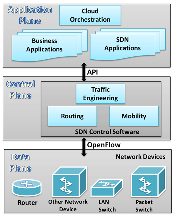
Figure 2: SDN component planes
The following video provides more details about software-defined networking.
SDN architecture
SDNs are remarkably flexible; they can operate with different types of switches and at different protocol layers. SDN controllers and switches can be implemented for Ethernet switches (Layer 2), Internet routers (Layer 3), transport (Layer 4) switching, and even at the application layer (Layer 7). SDN relies on the common functions found on networking devices, which essentially involve forwarding packets based on some form of flow definition.
From the point of view of an individual switch, a flow is a sequence of packets that matches a specific entry in a flow table. A flow table matches incoming packets to a particular flow and specifies the functions that will be performed on the packets. A combination of flow table entries on multiple switches binds a flow to a path.
In an SDN architecture, a virtual or physical switch performs the following functions:
- The switch encapsulates and forwards the first packet of a flow to an SDN controller, enabling the controller to decide whether the flow should be added to the switch flow table.
- The switch forwards incoming packets out the appropriate port based on the flow table. The flow table may include priority information dictated by the controller.
- The switch can drop packets on a particular flow, temporarily or permanently, as dictated by the controller, for security purposes. This function curbs denial-of-service (DoS) attacks or traffic management requirements (congestion control).
The SDN controller manages the forwarding state of the switches using APIs that allow the controller to address a wide variety of operator requirements without changing any of the lower-level aspects of the network, including topology.
With the decoupling of the control and data planes, SDN enables applications to deal with a single abstracted network device without concern for the details of how the device operates. Network applications see a single API to the controller. Thus it is possible to quickly create and deploy new applications to orchestrate network traffic flow to meet specific enterprise requirements for performance or security.
The centralized SDN controller can be used to effectively provision, manage, and tear down virtual networks over a physical IP fabric. The SDN controller provides a standardized API to a cloud-orchestrating application to program the network elements in a datacenter to provide on-demand virtual networks. In case a VM is migrated, the SDN controller will take care of modifying the flow tables in the network elements to re-establish the virtual network. This kind of flexibility cannot be provided if the configuration is done manually.
Using these techniques, SDNs create a logical overlay network that isolates the network components between different tenants, while simultaneously allowing VMs from the same tenant to exist on the same Layer 2 broadcast domain. This is allowed even if both devices physically reside in different datacenters. By abstracting away the physical network, cloud providers can then allocate both private and public (internet-facing) IP addresses to VMs, and even allow them to be dynamically relocated, without requiring any manual reconfiguration.
Isolation by using SDNs
Having a central controller allows the control plane to have a global view. This reduces the need for complex protocols like Spanning Tree Protocol to compute paths. Instead a simple shortest-path algorithm (for example, Dijkstra) can be used to compute the topology. This removes complexity from the central plane, allows fast reconfiguration of network architectures, and adds and updates security rules, all using a simple API.
Isolation between tenants is a critical SDN application on the cloud. In specifying separate network flows depending upon the tenant, multiple virtual networks can be overlaid on a single physical network. These virtual networks can even have overlapping IP address space. Consider the case of two cloud tenants, Yellow and Red, co-located on the same rack in the datacenter (Figure 3). They can share the same underlying infrastructure, while being isolated using a higher-level abstraction.
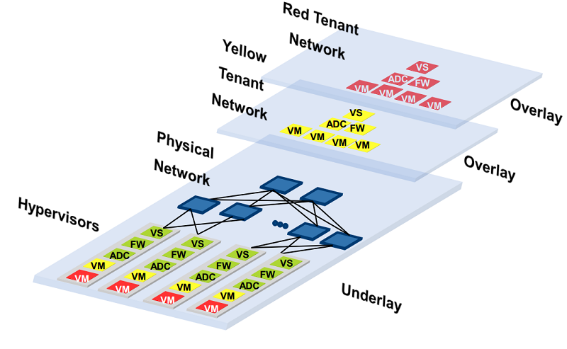
Figure 3: Logical view of a network overlay
One way to achieve isolation between the Red and Yellow tenant networks is by using network tunneling. Typically, the following steps take place for tunneling traffic:
The application running on the VM considers it attached to a LAN segment and sends out an Ethernet frame on the virtual network interface (VNI).
The vSwitch receives the packet from the VM and encapsulates it. The encapsulation method (Figure 4) may be either of the following:
- VXLAN (Virtual Extensible LAN)
- NVGRE (Network Virtualization using Generic Routing Encapsulation)
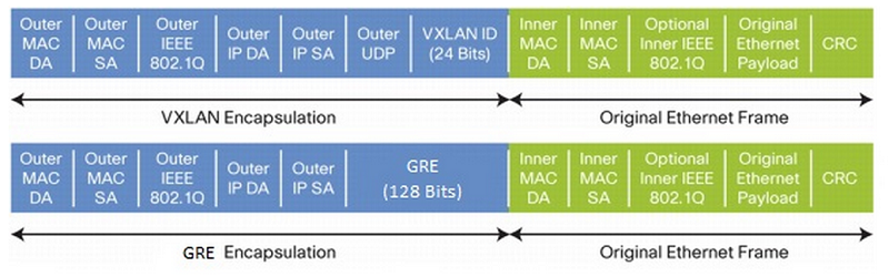
Figure 4: Encapsulation methods
The kernel IP stack adds the destination MAC and IP address of the target hypervisor and sends it out on the physical IP fabric.
At the destination, the kernel IP stack strips the outer MAC and IP address, reads the encapsulation headers to determine the destination VM, and delivers the packet to the VNI of the destination VM.
The overall flow of a packet from the source application to the destination application is illustrated in Figure 5.
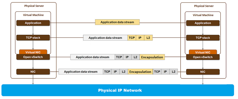
Figure 5: Packet stages in a virtualized network
Software-defined networking comes into the picture in steps 2 and 3 of the above tunneling process. The software running on the hypervisor vSwitch inspects the packets and requests the centralized SDN controller to add a flow specification. The flow specification is used to match the {VM, source address, destination address} tuple to a flow action that adds the encapsulation header and the outer MAC and IP header, as shown in Figure 5. The SDN controller knows what outer header to add because it has a global view of all the resources, and the software on the controller routes the flows accordingly.