Software-defined storage
As you have already seen, different types of storage systems can be deployed based on the needs of an application. The most basic form of storage is direct-attached storage, wherein storage devices such as magnetic disks or SSDs are directly attached to a server internally (through an internal bus connection, typically SATA or SAS). On the other hand, massive, enterprise-grade storage systems can be used in the form of a storage area network (SAN), which uses a network (using different technologies) to connect servers to a pool of disks.
Recall that in clouds, physical compute resources are shared among multiple tenants through virtualized servers. This approach could also apply to storage resources. Storage resources can be shared among multiple tenants, lowering cost and improving overall utilization of these resources. However, a form of isolation should be provided along with fault tolerance and other technologies to meet a specific application's SLOs. This enables clients to have predictable behavior for their applications, while sharing storage resources with other tenants. Providing end-to-end SLOs would translate into requirements for bandwidth, input/output operations per second (IOPS), priority, or control over the entire I/O path, as shown in the following figure.
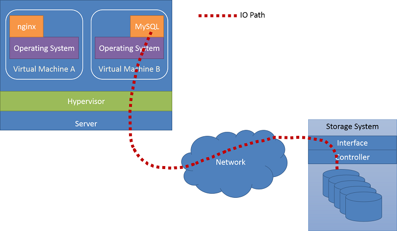
Figure 7: An example I/O path
Software-defined storage (SDS) allows clients to specify fine-grained capacity, latency, and/or bandwidth requirements, in the form of SLOs, which are mapped to abstract storage services for the client. The cloud provider can assemble and provide a scalable storage service using various storage technologies in the back end. Client SLOs can be met by managing the storage stack at the provider's side.
To better understand how this can be achieved, let's look at one of the emerging technologies that enable SDS, IOFlow.1
Example of SDS: IOFlow
In datacenters, the operation of an application requesting file operations and the storage system fulfilling the operations is complex and involves several stages, such as the host OS, the hypervisor, the network fabric, the storage server, and finally a disk operation. The request also appears differently at each layer. For example, a file I/O request like read, write, or create in a VM results in a block I/O request in the hypervisor. This, in turn, results in Ethernet packets across the network, and finally another file I/O request and block device request at the storage server.
The number of layers in the system means that enforcing an end-to-end flow policy (these policies are typically derived from an SLO) is hard. It requires layers along the I/O path to treat requests differently based on their content and/or client SLOs. Further, policies may need to be enforced at one or more or all layers along the path. For example, prioritizing I/Os from a specific VM to storage requires configuring the prioritization on all layers along the path.
IOFlow is a software-defined storage architecture, designed by Microsoft, to maintain end-to-end SLOs and bandwidth SLOs, and also improve performance. The clients are VMs running on compute servers through a hypervisor. These VMs need access to the storage server, which is regulated by IOFlow. Data flow is achieved by the use of queues at each stage in the I/O path. These queues are regulated by a centralized controller. The centralized controller in the IOFlow architecture assigns data-rate metrics and the route at each stage in the overall architecture.
An example of a typical I/O path from VM to storage server is presented in Figure 8. A compute server, which consists of a number of VMs running simultaneously, interacts with a storage server. Thus, the application interaction with a file system within a VM becomes block device requests at the virtual hard disk (VHD). In this specific example, the virtual hard disk is actually a remote storage server serving files by using Microsoft's SMB protocol. Therefore, I/O requests further get translated into a network packet at the hypervisor's network driver and sent across to the remote storage server through the network. In the storage server, the network packet is unwrapped at each layer, transforming into an SMB request, which in turn translates into a file system request at the storage server. At each layer in this I/O path, IOFlow adds a queuing abstraction, which is then exposed to the IOFlow controller. The controller can translate these policies into lower-level queuing rules at each stage.
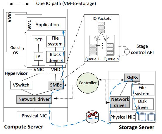
Figure 8: IOFlow example (Source)
The IOFlow controller regulates I/O traffic in the following manner:
- The IOFlow controller obtains a graph of the entire network under it, including where the compatible stages are located.
- Policies (explained below) supported by the controller are chosen by the client.
- Based on the client's policy, queues are formed and configured at intermediate stages.
- When I/O traffic passes through these intermediate stages, the I/O header is recognized and the respective policy is implemented.
IOFlow implements flow identifiers, which are basically I/O headers attached to individual I/O requests. These low-level headers are attached to the I/O as the high-level headers and cannot be recognized by the intermediate stages. Once the intermediate stages identify a header, they use it as routing information to route the I/O to the next hop.
As an example of how SDS can use policies to regulate I/O traffic, IOFlow currently presents the following five flow policies:
| Flow | Description |
|---|---|
| P1 | One VM (VM1) is guaranteed a fixed bandwidth, B. |
| P2 | When extra bandwidth is available, VM1 is allowed to exceed B. |
| P3 | Sanitize policy; the I/O traffic is routed through a sanitization layer (such as malware detection). |
| P4 | High priority; the data traffic of the VM2 must be given high priority from end to end. |
| P5 | Multiple VMs that belong to the same client and that access a common pool of resources can be guaranteed bandwidth B. |
For P1, every VM is promised a minimum bandwidth to access one or more storage servers. However, in P2, if there is extra bandwidth available as a result of one of the peer VMs having gone idle, the bandwidth available to VM1 can change dynamically. P3 requires traffic to be routed to a layer for sanitization. As an example, a new untrusted VM can have its traffic routed to a malware detection system. P4 can ensure low-latency operations by assigning high priority to VM2 storage traffic. P5 allows a bandwidth guarantee for a set of VMs that need to access specific storage servers. The policies P1 through P4 are specified for point-to-point flows, while P5 policies are specified for multiple flows.
SDS is a fast-evolving approach to providing storage as a service that meets a client's SLOs through shared storage systems. As mentioned above, sharing without end-to-end SLO guarantees will not be readily adopted. IOFlow is an early example of an SDS technology. We expect the innovation in the SDS space to continue at a rapid pace, bringing with it new solutions that will attempt to meet new cloud application requirements.
References
- Thereska et al. (2013). IOFlow: A Software-Defined Storage Architecture SOSP'13: The 24th ACM Symposium on Operating Systems Principles