Azure Sphere – SPI
This sample demonstrates how to use SPI with Azure Sphere in a high-level application.
The sample displays data from an ST LSM6DS3 accelerometer connected to an MT3620 development board through the Serial Peripheral Interface (SPI). The accelerometer data is retrieved every second and is displayed by calling the Applibs SPI APIs.
The sample uses the following Azure Sphere libraries.
| Library | Purpose |
|---|---|
| eventloop | Invokes handlers for timer events. |
| log | Displays messages in the Device Output window during debugging. |
| spi | Manages the Serial Peripheral Interfaces (SPIs). |
Contents
| File/folder | Description |
|---|---|
app_manifest.json |
Application manifest file, which describes the resources. |
CMakeLists.txt |
CMake configuration file, which Contains the project information and is required for all builds. |
CMakePresets.json |
CMake presets file, which contains the information to configure the CMake project. |
launch.vs.json |
JSON file that tells Visual Studio how to deploy and debug the application. |
LICENSE.txt |
The license for this sample application. |
main.c |
Main C source code file. |
README.md |
This README file. |
.vscode |
Folder containing the JSON files that configure Visual Studio Code for deploying and debugging the application. |
HardwareDefinitions |
Folder containing the hardware definition files for various Azure Sphere boards. |
Prerequisites
This sample requires the following hardware:
An Azure Sphere development board that supports the Sample Appliance hardware requirements.
Note: By default, the sample targets the Reference Development Board design, which is implemented by the Seeed Studios MT3620 Development Board. To build the sample for different Azure Sphere hardware, change the value of the TARGET_HARDWARE variable in the
CMakeLists.txtfile. For detailed instructions, see the Hardware Definitions README file.A breadboard (recommended because this sample requires wiring from multiple sources to the same pin)
Jumper wires to connect the boards
Setup
Ensure that your Azure Sphere device is connected to your computer, and your computer is connected to the internet.
Ensure that you have Azure Sphere SDK version 24.03 or above. At the command prompt, run
az sphere show-sdk-versionto check. Upgrade the Azure Sphere SDK for Windows or Linux as needed.Ensure that the Azure CLI is installed. At a minimum, the Azure CLI version must be 2.45.0 or later.
Install the Azure Sphere extension.
Enable application development, if you have not already done so, by entering the
az sphere device enable-developmentcommand in the command prompt.Clone the Azure Sphere samples repository and find the SPI_LSM6DS3_HighLevelApp sample in the SPI folder or download the zip file from the Microsoft samples browser.
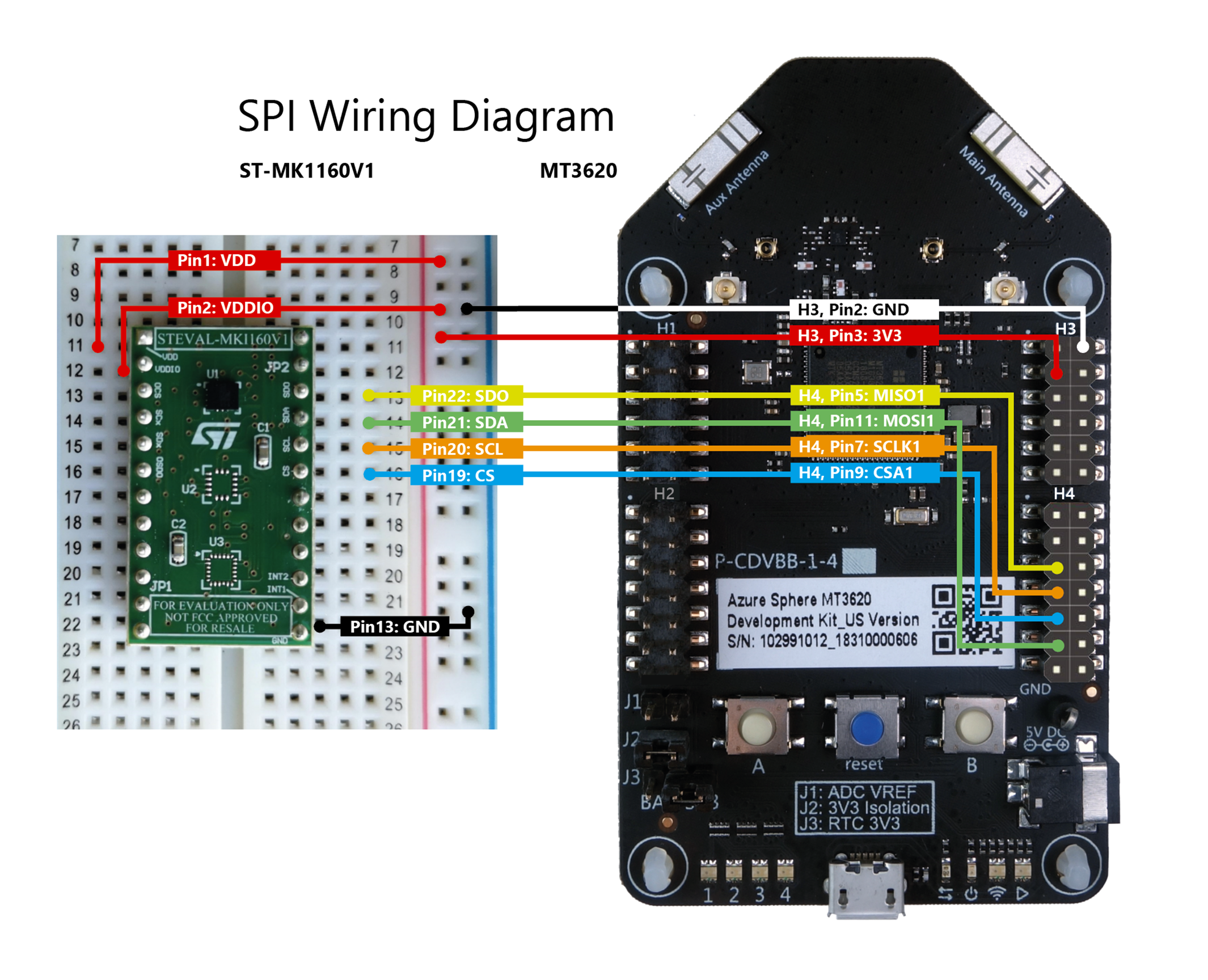
Set up the ST LSM6DS3 connections
Make the following connections between the ST LSM6DS3 and MT3620 dev boards. Make sure that power is disconnected while you wire the boards.
Note: By default, this sample is configured to use an external ST LSM6DS3 and isn't configured to use the onboard sensors found on some development boards, such as the ST LSM6DS0 on the Avnet Starter Kit. This sample uses ISU1 on the MT3620 board; however, you can use another ISU by adjusting the wiring, the code, and the application manifest.
Build and run the sample
To build and run this sample, follow the instructions in Build a sample application.
Test the sample
When you run the application, it reads the WHO_AM_I register from the accelerometer. This should return the known value 0x69, which confirms that the MT3620 can successfully communicate with the accelerometer. If this fails, verify that the devices are wired correctly, and that the application opened the correct SPI interface. For details on the registers, see the ST LSM6DS3 data sheet.
After displaying the initial values, the application configures the accelerometer and then displays the vertical acceleration every second.
To test the accelerometer data:
Keep the device still, and observe the accelerometer output in the Device Output window. Once the data from the CTRL3_C register is displayed, the output should repeat every second.
Turn the accelerometer upside down and observe the updated data in the Device Output window. The vertical acceleration should change from approximately +1g to approximately -1g.
Next steps
- For an overview of Azure Sphere, see What is Azure Sphere.
- To learn more about Azure Sphere application development, see Overview of Azure Sphere applications.